


1 GENERAL
1 .Ol
This chapter provides procedures for installa-
tion of STRATA DK system printed circuit boards
(PCBs). This includes installation instructions, PCB
optional configuration information, and wiring and
programming considerations for each PCB.
1.02 Begin PCB installation only after completion
of KSU installation.
NOTE:
Be sure the power supply has been tested,
and the ground has been checked.
2 PCB INSTALLATION OVERVIEW
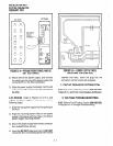
2.01 STRATA DK system KSUs are shipped with
only the power supply installed. No PCBs are
included. PCBs must be installed in accordance
with the configuration information obtained and
developed in System Configuration, Section 200-
096-204.
2.10 PCB Installation Considerations
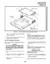
2.11
The PCTU or PCTUSI (DK24 only) PCB
must be installed in the PCTU slot. PCB slots SO1
- SO6 (DK24), PCB slots SO1 - SO8 (DK56), and
PCB slots SO1 a S14 (DK96) are universal; any of
the optional PCBs may be installed in any available
slot, as long as the system is programmed to
recognize the chosen configuration. However, it is
recommended that station PCBs (PEKUs, PSTUs,
PESUs), and CO line/E & M TIE line PCBs (PCOUs
and PEMUs) be installed in a certain order. Use of
these configuration recommendations will reduce
reprogramming in future system expansion, and
keep the system station and CO line numbering
scheme simple.
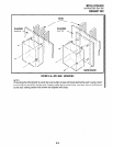
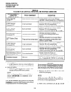
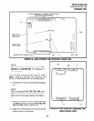
2.12 DK24/56/96 PCB Configuration Recom-
mendations.
First install station PCBs (PEKU,
PSTU, and PESU) from left to right and then CO
line/E & M TIE line PCBs (PCOUs and PEMUs)
from left to right, and optional PCBs (PIOU, PIOUS
or PEPU) from right to left, so that vacant slots are
in the middle.
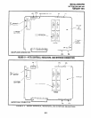
2.20 Recommended Universal PCB Slot
Assignments
INSTALLATION-PCB
SECTION 200-096-206
FEBRUARY 1991
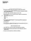
2.21 The following steps describe the recom-
mended installation order and slot assignments for
STRATA DK system station, line, and peripheral
PCBs. Installation order is the same for all systems.
1)
2)
3)
Install all PEKU PCBs, from left to right, start-
ing with slot 01. Do not skip slots.
Then install all PSTU PCBs, from left to right,
starting with the lowest numbered empty slot.
Do not skip slots.
Then install all PESU PCBs, from left to right,
starting with the lowest numbered empty slot.
Do not skip slots.
NOTE:
Normally, one PEW is installed instead of a
PEKU or PSTU in configurations that require
less than three standard telephone ports or
less than five electronic telephone ports.
4)
5)
6)
Then install all PCOU PCBs, from left to right,
starting with the lowest numbered empty slot.
Do not skip slots.
Then install all PEMU PCBs, from left to right,
starting with the lowest numbered empty slot.
Do not skip slots.
Install a PIOU, PIOUS, or PEPU in the last slot
(slot 06 in DK24, slot 08 in DK56, or slot 14 in
DK96).
2.30 Station and Line Expansion
2.31 If station or line PCBs (PEKU, PSTU, PESU,
PCOU, and/or PEMU) must be added to an existing
installation, install the PCBs in the order recom-
mended in Paragraph 2.20, starting with the lowest
numbered empty slot. For example, if it is neces-
sary to add eight standard telephones and four CO
lines, install a PSTU PCB in the lowest numbered
empty slot and then a PCOU PCB in the next empty
slot. Do not skip slots.
2.32 If PEKU, PSTU, PERU and/or PCOU PCBs
are added, it is advisable to move any PEMU PCBs
to the right to make room for the new PCBs.
6-1