


INSTALLATION-PERIPHERALS
SECTION 200-096-208
FEBRUARY 1991
6) To terminate the call anytime:
a) If off-hook, press the m bar and
place the DKT handset on-hook.
b) If talking via the speakerphone, press the
m bar.
13 TWO-CO LINE EXTERNAL
AMPLIFIED CONFERENCE (RELEASE 3)
13.00 General.
13.01
Customer-supplied two-way amplifiers can
be installed to amplify two-CO line tandem and/or
conference calls. As many as four amplifiers can be
installed to support up to four of these calls occur-
ring simultaneously. If three amplifiers are installed,
three simultaneous calls can be supported, and so
on. If all amplifiers are being used, then subsequent
two-CO line tandem calls and/or conference calls
will be unamplified. Each amplifier is connected to
two designated PEKU station ports and will auto-
matically be switched into a two-CO line connection
established between any CO lines in the system.
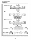
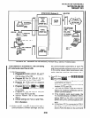
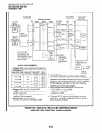
13.02 Amplified Talk Path.
Figure 8-40 pro-
vides a functional diagram of a two-CO line
amplified conference connection (an R-TEC
VFR5050 amplifier is used here). The talk
path for the connection is as follows: outside
party 1 -public telephone network-PCOU,
CKTX-PCTU3-PEKU, port A-into AMP,
CKTA-Out AMP, CKT B-PEKU, port B-
PCTU3-PCOU, CKTY-public telephone
network-outside party 2. This path is two-
way so when outside party 2 talks, the talk
level is amplified in the reverse direction.
NOTE:
Only the outside party 1 talk path is amplified
to/from a system telephone when it is con-
nected into a two-CO line conference.
13.03 Amplifier Requirements
l
Customer-supplied (four maximum).
l
Must be FCC-registered, Part 68, and
provide automatic gain control.
l
Each amplifier requires two PEKU sta-
tion ports.
l
Refer to the amplifier manufacturer’s in-
stallation documentation for amplifier
grounding instructions.
.
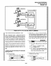
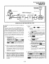
13.04 Installation:
Connect a two-way amplifier to
the STRATA DK system in accordance with the
following steps (see Figures 8-40 and 9-24).
1) At the main distribution frame (MDF), connect
the voice pair (VT, VR, port A) of circuit 2 on
the designated PEKU PCB to one input of the
customer-supplied two-way amplifier. In the
example in Figure 8-40, this is CKTA (Central
Office Side A) of the VFR5050.
2) At the MDF, connect the voice pair (VT, VR,
port B) of circuit 3 on the designated PDKU
PCB to the other input of the amplifier. In the
Figure 8-40 example, this is CKTB (subscriber
side B) of VFR5050.
3) Plug the amplifier’s power cord into the 117
VAC (standard) wall outlet.
4) Set the gain and other amplifier parameters
options per the amplifier manufacturer’s in-
stallation documentation.
5) Program the STRATA DK system as follows:
l
Program 10-3:
Enables the appropriate
PEKU PCB ports for amplifier connec-
tion. Only enable the ports that will be
connected with the amplifier(s).
l
Program 15-5:
Enables appropriate CO
lines for tandem connection.
l
Program IO-I
: LEDs 19 and 20 must be
ON.
l
Program 10-2:
LED 18 must be ON.
NOTE:
LED 19 should be ON if it is certain that an
amplifier will always be available for two-CO
line conference connection (four maximum,
simultaneously). If this LED is ON and a
two-CO line connection is established without
an external amplifier, the STRATA DKstation
may be unbalanced and receive a hum noise.
LED 19 provides additional station amplifica-
tion when externalamplifiers areswitchedinto
two-CO line connections.
8-62