


INSTALLATION-SYSTEM DESCRIPTION
SECTION 200-096-202
FEBRUARY 1991
1 GENERAL 2 SYSTEM TECHNOLOGY
1.00
This chapter provides a discussion of the
technology employed in the STRATA DK system
design, and a detailed description of the system
hardware, including the basic equipment cabinet
(key service unit), PCB options, and system pe-
ripheral equipment. A description of system con-
trols and indicators is also provided.
1 .I 0 System Description
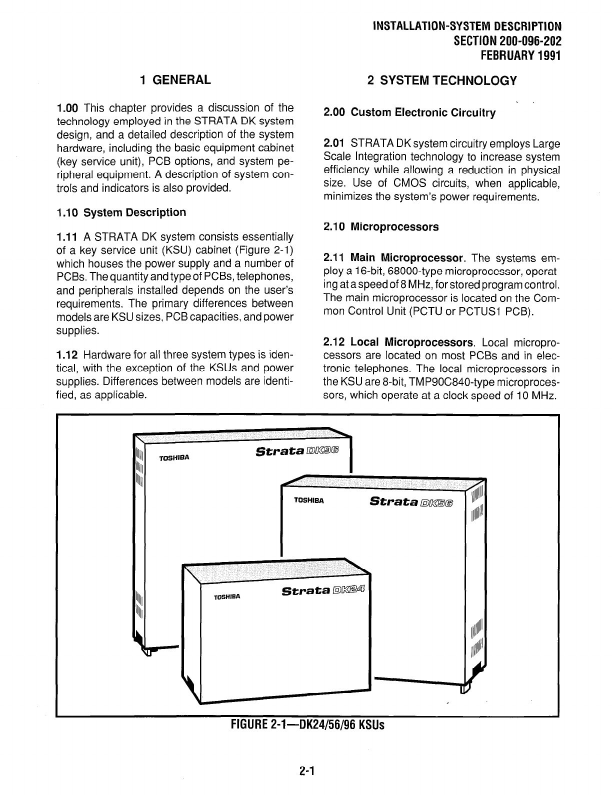
1 .I 1
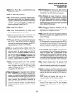
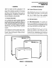
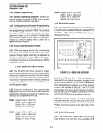
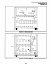
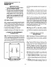
A STRATA DK system consists essentially
of a key service unit (KSU) cabinet (Figure 2-l)
which houses the power supply and a number of
PCBs. The quantity and type of PCBs, telephones,
and peripherals installed depends on the user’s
requirements. The primary differences between
models are KSU sizes, PCB capacities, and power
supplies.
1.12 Hardware for all three system types is iden-
tical, with the exception of the KSUs and power
supplies. Differences between models are identi-
fied, as applicable.
2.00 Custom Electronic Circuitry
2.01 STRATA DK system circuitry employs Large
Scale Integration technology to increase system
efficiency while allowing a reduction in physical
size. Use of CMOS circuits, when applicable,
minimizes the system’s power requirements.
2.10 Microprocessors
2.11 Main Microprocessor.
The systems em-
ploy a 16-bit, 68000-type microprocessor, operat-
ing at a speed of 8 MHz, for stored program control.
The main microprocessor is located on the Com-
mon Control Unit (PCTU or PCTUSI PCB).
2.12 Local Microprocessors.
Local micropro-
cessors are located on most PCBs and in elec-
tronic telephones. The local microprocessors in
the KSU are 8-bit, TMP90C840-type microproces-
sors, which operate at a clock speed
of 10 MHz.
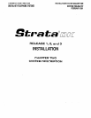
llllll
StrataDKB@ StrataDKB@
illill Illill
TOSHIBA TOSHIBA
lllll/ lllll/
TOSHIBA TOSHIBA
Strata izmsm Strata izmsm
~~lllll~~’
lllllll~l’
TOSHIBA TOSHIBA
FIGURE Z-l--DK24/56/96 KSUs
2-1