


INSTALLATION-PERIPHERALS
SECTION 200-096-208
FEBRUARY 1991
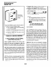
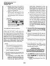
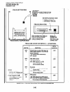
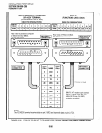
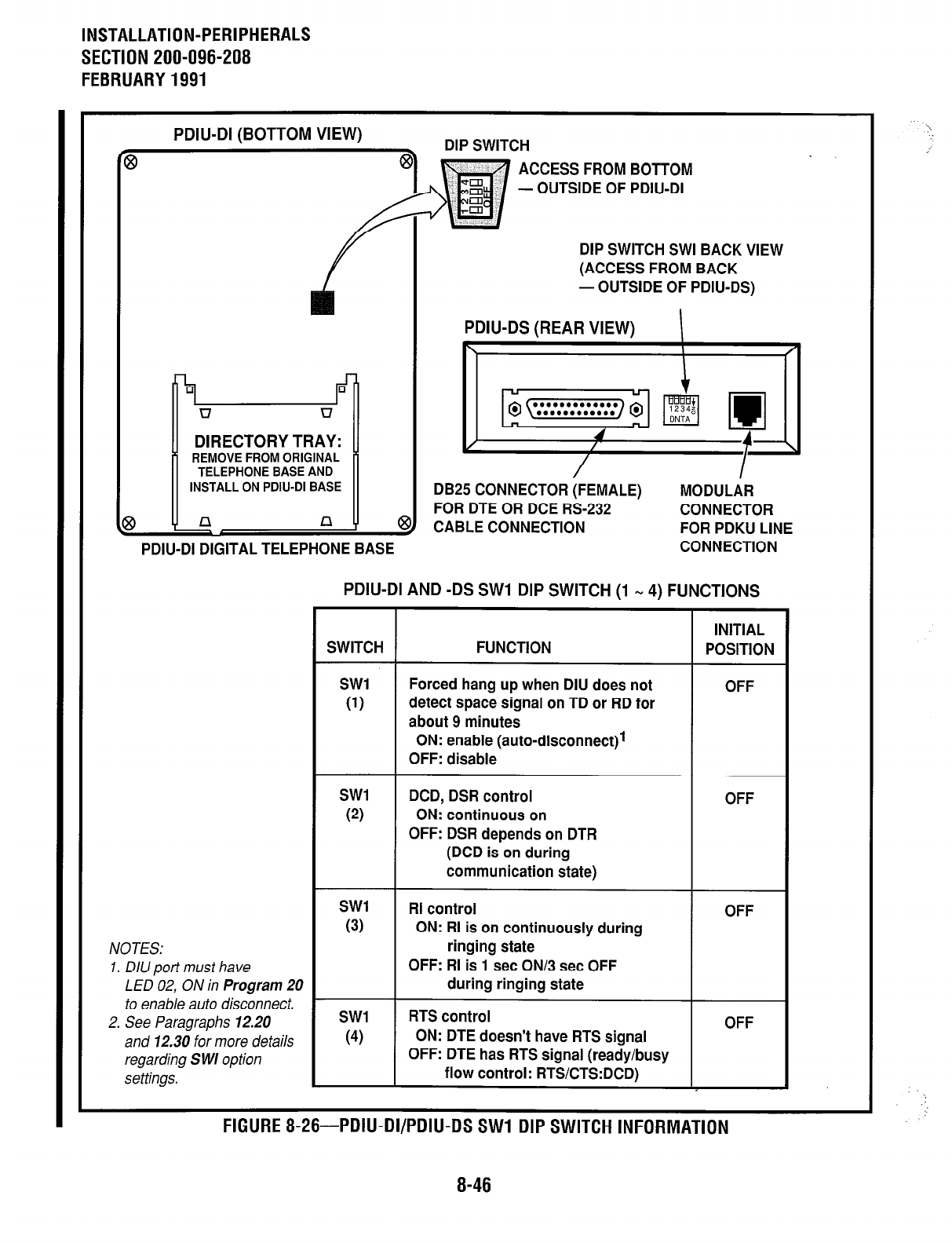
PDIU-DI (BOTTOM VIEW)
DIP SWITCH
8
ACCESS FROM BOTTOM
- OUTSIDE OF PDIU-DI
r
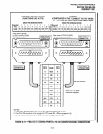
DIP SWITCH SWI BACK VIEW
(ACCESS FROM BACK
- OUTSIDE OF PDIU-DS)
n u
DIRECTORY TRAY:
’ REMOVE FROM ORIGINAL ’
TELEPHONE BASE AND
INSTALL ON PDIU-DI BASE
4
3
f n
n -
q
PDIU-DI DIGITAL TELEPHONE BASE
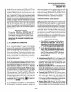
PDIU-DS (REAR VIEW)
I
I
DB25 CONNECTOR (FEMALE)
MODULAR
FOR DTE OR DCE RS-232
CONNECTOR
CABLE CONNECTION
FOR PDKU LINE
CONNECTION
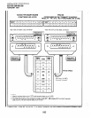
NOTES: NOTES:
1. DIU port must have
LED 02, ON in Program 20
to enable auto disconnect. -
2. See Paragraphs 12.20
and 12.30 for more details
regarding S WI option
settings.
1. DIU port must have
LED 02, ON in Program 20
to enable auto disconnect.
2. See Paragraphs 12.20
and 12.30 for more details
regarding S WI option
settings.
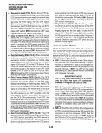
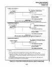
PDIU-DI AND -DS SW1 DIP SWITCH (1 _ 4) FUNCTIONS
fi
SWITCH
FUNCTION
INITIAL
POSITION
SW1
(1)
Forced hang up when DIU does not
detect space signal on TD or RD for
about 9 minutes
OFF
ON: enable (auto-disconnect)l
OFF: disable
SW1
(2)
DCD, DSR control
ON: continuous on
OFF: DSR depends on DTR
(DCD is on during
OFF
communication state)
SW1
(3)
RI control
ON: RI is on continuously during
ringing state
OFF
OFF: RI is 1 set ON/3 set OFF
during ringing state
SW1
(4)
RTS control
ON: DTE doesn’t have RTS signal
OFF: DIE has RTS signal (ready/busy
flow control: RTS/CTS:DCD)
OFF
FIGURE 8-26-PDIU-DVPDIU-DS SW1 DIP SWITCH INFORMATION FIGURE 8-26-PDIU-DI/PDIU-DS SW1 DIP SWITCH INFORMATION
8-46