


PROGRAMMING PROCEDURES-INTRODUCTION
SECTION 200-096-301
FEBRUARY1991
another vowam
more data
1
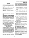
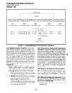
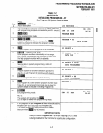
~T;l~T;l~~s,,,n~~fispKRIg*~!~lT;;lT;;l~!SPKR~~~
/~--7--\---T--
Step 1
Step 2 Step 3
Step 4 Step 5
Enter Program Mode
Enter Program Number Enter Program Data Exit Current Program Exit Program Mode
\,
; *\ I
-:
‘0
:- (LED buttons)
-.
I
and/or
tl-II
FIGUREI-I-PROGRAMMINGBUTTONSEQUENCEOVERVIEW
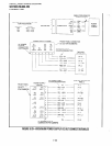
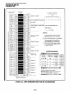
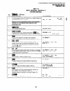
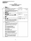
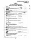
3.23 Multidimensional Programs:
Once a pro-
gram number is entered, the first dimension (usu-
ally a CO line number, a station port number, or a
range of ports) must be specified. Upon specifying
this first dimension on the dialpad, programming
button LEDs 01 N 36 light in the default configura-
tion. The status of each LED can be changed by
pressing its associated button. Pressing the button
while its LED is lit turns the LED off; pressing the
button while its LED is off turns the LED on.
Pro-
gram
30 is a multidimensional program; see Table
1-B for step-by-step data entry instructions for
Program 30.
l
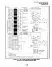
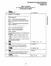
Range Programming:
When programming a
range of station ports, the station’s program-
ming LEDs indicate whether the data pro-
grammed matches for all items in the range:
l LED On:
Indicates that all ports in the range
are programmed with the data choice that
lights the particular LED.
l LED Off:
Indicates that all ports in the range
are programmed with the data choice that
does not light the particular LED.
l LED Flashing:
Indicates that data is cur-
rently inconsistent for all ports in the range.
Some may be programmed with the LED
on; some with the LED off.
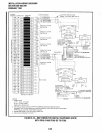
3.24 Programming Button/LED Buttonstrip
Template:
A special buttonstrip template is placed
over the 20 buttons located to the right of the
dialpad on the programming LCD electronic tele-
phone, or over the 20 buttons above the dialpad on
the programming LCD digital telephone. The tem-
I
plate assigns numbers to each of the 20 buttons
that coincidewith tables found in the System Record
for programming purposes. It includes assignments
for on-hook programming, to identify programming
LED buttons 01 -- 20; and assignments for off-hook
programming, to identify programming LED but-
tons 21 N 36 (shaded). Templates are supplied with
each manual.
3.30 Preparing the System for Programming
3.31 This section explains how to prepare a sys-
tem for programming, including minimum hard-
ware requirements, and directions to clear the
system’s memory.
3.32 Minimum Hardware Requirements:
A sys-
tem must have the following minimum hardware
installed for programming, as described in Instal-
/&ion, Section 200-096-209:
l Power Supply:
The power supply must test
satisfactorily.
1-2