


1 GENERAL
1
.OO This chapter provides procedures necessary
to connect optional peripheral equipment to
STRATA DK systems. The installation instructions
for each peripheral option include hardware re-
quirements, PC6 configuration, interconnection/
wiring requirements, and programming considera-
tions, as applicable.
1
.Ol Peripheral equipment is connected to system
PCBs. Refer to PCB Installation, Section 200-096-
206, for PCB installation instructions and PCB
configuration information.
1.02
Figures are located in the middle and at the
end of this chapter.
2 RESERVE POWER/POWER FAILURE
OPTIONS
2.00 STRATA DK systems offer two options to
protect system operation in the event of a power
failure; the Reserve Power option, and the Power
Failure Emergency Transfer option.
2.10 Reserve Power Option
2.11
STRATA DK system power supplies provide
the capability of connecting a reserve power source
(battery backup) to ensure uninterrupted system
operation in the event of a power failure. A pre-
assembled interface cable for installation of the
Reserve Power option is available from Toshiba
(PBTC-3M).
2.12 Refer to KSU Installation, Section 200-096-
205, for site requirements for the reserve power
batteries.
IMPORTANT NOTE!
Local ordinances may dictate battery type
and installation details.
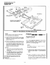
2.13 Reserve Power Installation.
Install the Re-
serve Power option in accordance with the follow-
ing steps (refer to Figure 8-l):
1) Connect the
PBTCSM
black jumper wire from
the positive terminal of one 12VDC battery to
the negative terminal of the second 12VDC
battery.
INSTALLATION-PERIPHERALS
SECTION 200-096-208
FEBRUARY 1991
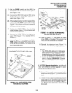
2) Ensure that a serviceable lo-ampere fuse is
installed in the in-line fuse holder of the
,PBTC-
3M
battery cable.
3) Connect the white lead of the
PBTC-3M
bat-
tery cable to the open positive terminal of the
12VDC battery. Connect the black lead to the
open negative terminal of the second 12VDC
battery.
IMPORTANT NOTE!
The KSU must be connected to the AC
power source, and the power supply ON/
OFF switch set to ON prior to the final step
of connecting the reserve power batteries
to the po wer supply via the BA TT +/- recep
tacle. If the batteries are connected after
AC power is lost, reserve power will not
function.
4) Connect the
PBTC3M
battery cable two-prong
male plug to the power supply BATT +/- re-
ceptacle.
5) To test reserve power operation, disconnect
the system AC power plug with the power
supply power
ON/OFF
switch in the ON po-
sition. The system should continue to operate
without any interruption.
NOTE:
See Paragraph 14 for battery care require-
ments. I
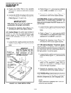
2.20 Power Failure Emergency Transfer Op-
tion
2.21
The Power Failure Transfer Unit (DPFT) pro-
vides a means of automatically connecting up to
eight selected CO lines directly to designated stan-
dard telephones in the event of a power failure. The
DPFT allows normal operation of the selected CO
lines and standard telephones when the system is
in service. When power is restored, each telephone
is independently reconnected to the system after
that telephone is finished with its direct CO line call.
The DPFT is normally installed on the Main Distri-
bution Frame (MDF).
2.22 A circuit diagram of the DPFT is shown in
Figure 8-2.
8-l