


INSTALLATION-TELEPHONE
SECTION 200-096-207
FEBRUARY1991
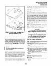
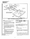
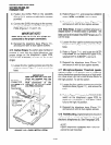
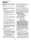
3) Position the DVSU PCB on the standoffs
(Figure7-12),andsecurewiththefourscrews
provided.
4) Connect the DVSU wire plugs to the connec-
tors labelled DVSU on both of the telephone’s
PCBs (Figures 7-l 1 and 7-12).
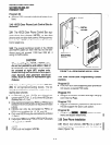
IMPORTANT NOTE!
Make sure that the DVSU wire plugs are
connected to the proper connectors.
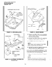
5) Reinstall the telephone base (Figure 7-l),
and secure it with its four captive screws.
4.15 Carbon Straps:
If a carbon-type handset or
headset is used with the digital telephone, two
jumper straps on the telephone’s upper PCB,
labelled DKT-SUB(SPF), must be cut. To cut the
straps:
1) Loosen the four captive screws securing the
telephone base (Figure 7-l), and remove the
base.
IMPORTANT!
Make sure that the DVSU wire
TO DVSU
plugs are inserted into the
correct UPPER and LOWER
CONNECTOR
PC0 connectors of the
ON UPPER
PCB
telephone. Do not plug DVSU
INSIDE into HHEU connector.
TELEPHONE
FlGURE7-12-OVSUINSTALLATION
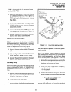
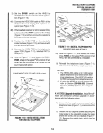
2) Refer to Figure 7-l 1, and locate the CARBON
straps,
W301
and W302, and cut them.
.
3) Reinstall the telephone base (Figure 7-l),
and secure it with its four captive screws.
4.16 Beep Strap.
A beep is emitted whenever a
dialpad button or flexible button is pressed. This
beep can be eliminated if the BEEP strap is cut. To
cut the strap:
1) Loosen the four captive screws securing the
telephone base (Figure 7-l), and remove the
base.
2) Refer to Figure 7-l 1, and locate the BEEP
strap,W304, on the telephone’s upper PCB,
labelled DKTl O-SUB(SPF), and cut it.
3) Reinstall the telephone base (Figure 7-I)
and secure it with its four captive screws.
4.17 Microphone/Speaker Threshold (speak-
erphone only).
If the speaker cuts off frequently
during handsfree operation because of high ambi-
ent noise levels, set the ROOM NOISE switch to
the high position. To set the switch:
1) Loosen the four captive screws securing the
telephone base (Figure 7-l ), and remove the
base.
2) Refer to Figure 7-l 1, locate the ROOM NOISE
switch on the telephone’s upper PCB, la-
belled DKTlO-SUB(SPF), and push it care-
fully to the high (H) position.
3) Reinstall the telephone base (Figure 7-l),
and secure it with its four captive screws.
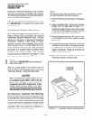
4.18 Wall Mounting.
Digital telephones mount on
walls and other vertical surfaces the same way
electronic telephones do. See Paragraph 3.13.
NOTE:
Digital telephones equipped with PDIU-Dls
cannot be wall mounted.
7-10