


INSTALLATION-PERIPHERALS
SECTION 200-096-208
FEBRUARY1991
l
LED
02: Should be OFF for PDIU-DS
ports connected to printers.
l
LED 03:
Should be OFF for PDIU-DS
ports that connect to DTE- or DCE-type
printers.
l
LED 04:
Should always be ON for PDIU-
DS ports.
l
LED
05: Should be OFF for PDIU-DS
ports connected to printers.
l
LEDs
17 -, 20: Data security groups can
be used to allow or deny digital telephones
equippedwith PDIU-Dlsaccessto PDIU-
DS ports connected to a printer. DIU
stations can only make datacalls to DlUs
in the same data security group.
7) Program
22should be used to configure PDIU-
DSs to hunt if more than one PDIU-DS con-
nected to the same printer/server.
lines and modems, it is recommended to connect
modems to PSTU/PESU standard station ports in
a modem pool configuration. The RS-232 side of
the modem connects to the PDIU-DSwith standard
RS-232 cables; the PDIU-DS line side (RJ-11 con-
nector) always connects to its own individual PDKU
port. Use the instructions below to install modems
to PDIU-DSs.
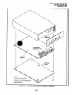
1) Configure the PDIU-DS as a DTE device:
Disassemble the PDIU-DS and place jumper
plugs
Pl
y
P9
in the”B-C’position (MODEM).
Reassemble the PDIU-DS and mark “B-C” on
the bottom identification label for future refer-
ence. (Paragraph 12.70 provides PDIU-DS
disassembly/assembly instructions and Fig-
ure 8-28 provides jumper plug information.)
2) Connect the PDIU-DS to the appropriate PDKU
circuit per the wiring diagrams in Section 200-
12.60 PDIU-DS To Modem Installation
12.61
With
Release
3 software, STRATA DK en-
ables asynchronous-type (not synchronous) mo-
dems to be connected to PDIU-DSs. This allows
PDIU-DI equipped digital telephones that are con-
nected to personal computers, terminals, and other
devices to share access to a modem or modem
pool.
IMPORTANT NOTE!
Modems must be “smart modems” that
respond to ATcommandsandreturn result
codes. Modems are customer-supplied.
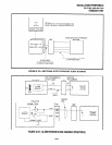
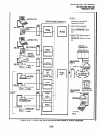
12.62 A modem(s) can be accessed internally for
outgoing data calls or externally for incoming data
calls. Modems operate as DCE devices; so PDIU-
DSs that are connected to them must be configured
to operate like a DTE device. In the example
installation in Figure 8-25, the line side of the two
modems are connected to PSTU/PESU ports to
establish a modem pool; however, the line side of
modems could be connected directly to a dedicated
CO line. If modems are connected directly to tele-
phone network CO lines, automatic transfer of CO
line voice calls to system modems (data call) will
not function as described in the Data Interface User
Guide. For best operation and utilization of CO
096-209.
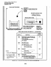
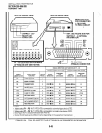
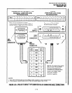
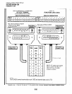
3) Connect the appropriate RS-232 cable be-
tween the modem and the PDIU-DS. Figure8-
32 shows an example PDIU-DS to “smart
modem” RS-232 connection.
IMPORTANT NOTE!
All ten PDIU-DS EIA leads (signals) should
be connected to the modem. Consult the
modem’s documentation for correct RS-
232 pin requirements; the requirements
may vary with each manufacturer.
4) Connect the line side of the modem to a PSTU
or PESU standard telephone circuit or a
dedicated CO line (consult the modem’s
documentation to install the it to a CO line).
Section 200-096-209 provides PESU/PSTU
station port wiring information.
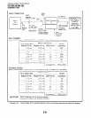
5) Set the PDIU-DS DIP switch
(SWl-1 - 4)
for
thedesiredapplication. Figure8-26shows the
DIP switch location and Paragraph 12.30
describes switch functions.
6) Use the programs below to configure the
PDIU-DS to connect to an asynchronous
modem (see programming Section 200-096-
302 for explanations and record sheets).
8-43