


INSTALLATION-PERIPHERALS
SECTION 200-096-208
FEBRUARY1991
l
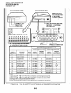
SWI-4:
This switch is placed in the ON position
if the computer does not output the RTS signal.
Sometimes, the DTE device may use RTSKTS
for Ready/Busy flow control, in these cases
SWl-4
should be OFF. In this case the DCD
signal of the calling DTE is used as the RTS lead
of the called DTE and the DCD signal of the
called DTE is used as the RTS signal of the other
DTE. In this case a signal which stops the DTE
from transmitting data (usually the CTS lead)
should be cross-connected to the DIU’s DCD
signal. Consult the DTE device or application
software documentation to determine which type
of flow control is required.
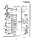
12.40 PDIU-DI to Personal Computer (PC) In-
stallation
12.41
The PDIU-DI always functions as a DCE
device; it transmits data on the Receive Data lead
(RD) and receives data on the Transmit Data lead
(TD). Most personal computers function as a DTE
device; PCs transmit data on the TD lead and
receive data on the RD lead. Follow the steps below
to install the PDIU-DI to a DTE, PC:
NOTES:
1. Use the steps below when installing an
ASCII terminal, personal computer, or any
other DTE device to a PDIU-DI.
2. The PDIU-DI can connect to a DCE
computer or any other DCE-type device
using a specially configured W-232 cable
or adapter; but this application is rarely
required.
1) Install the digital telephone that is to be
equipped with PDIU-DI per the instructions in
Section 200-096-207 and the drawing in Sec-
tion 200-096-209.
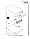
2) Install the PDIU-DI under the digital telephone
per the instructions in Section 200-096-207.
NOTE:
The PDIU-DI always operates as a DCE de-
vice; therefore, unlike the PDIU-DS, it has no
internal jumpers.
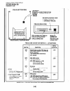
3) Connect the appropriate RS-232 cable be-
tween the PDIU-Dl’s DB-25female connector
and the PC’s appropriate asynchronous serial
communications port connector (C‘OM port).
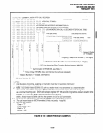
IMPORTANT NOTE!
Check the PC manufacturer’s serial com-
munica tion port interface documentation
for correct RS-232 pin requirements; re-
quirements vary with each manufacturer.
The number of ElA RS232signals required
(8, 9, or IO wires) depends on the applica-
tion. When EIA signal requirements are not
known, connect the 10 EIA signals listedin
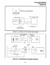
Paragraph 12.20. Figures 8-29 and 8-30
provide diagrams for connecting RS-232
cables between PDIU-Dls and Toshiba lap
top, and IBM, XT and AT PCs.
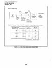
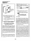
4) SetthePDIU-DI DIPswitch
(SWl-I-4)forthe
desired application. Figure 8-26 shows the
DIP switch locations and Paragraph 12.30
describes switch functions.
5)
Access
Program
20 to configure the PDIU-DI
for DTE-type connection and
Program 39
for
data button assignments of the digital tele-
phone connected to the PDIU-DI.
Program 20
l
The port number entered for the PDIU-DI
in
Program
20 is the port number of the
digital telephone to which the PDIU-DI is
connected.
l
LED 01:
Should always be ON for PDIU-
DI ports.
l
LED
02: Should be ON for PDIU-DI ports,
unless the PC user will never use DIU AT
commands (other than ATDD, ATDT,
and ATD) and never require the PDIU-DI
to send result codes to display on the PC
display screen. Frequently, it is difficult to
determine the full extent of these re-
quirements; so it is recommended to turn
LED 02 ON. See the Data Interface User
Guidein the Operating Procedures of the
Installation and Maintenance Manualfor
information regarding D!U ATcommands
and result codes.
l
LEDs
03
and
04: Should be OFF for
PDIU-DI ports.
8-41