


INSTALLATION-CONFIGURATION
SECTION 200-096-204
FEBRUARY1991
netted to one HDCB.
l
A maximum of four HDCBs are allowed per
system with PCTU(l, 2, or 3) and three with
I
PCTUSl .
l
One PEKU or PESU circuit, always circuit num-
ber 5, is required per HDCB. PDKU does not
I
support the HDCB.
l
HDCBs can only be connected to PEKU or
PESU port numbers 04, 12,20, and 28.
l
Always install HDCBs to PEKU or PESU PCBs
that are in lower slot numbers than PEMU PCBs.
This is required to maintain alignment of PEKU
and/or PESU circuit 5 and PEKU and/or PESU
port numbers 04, 12,20, and 28.
l
HDCBs do not require a special PCB code in
Program 03.
l
HDCB assignments are found in
Programs 77-
1, 77-2, and 79.
l
Door phones can be programmed to ring at any
I
digital and electronic telephone (no limit within
the system).
l
Door phones do not ring standard telephones .
l
Cut
W9
on all PEKUs and PESUs that support an
HDCB.
4.30 DSS/DDSS Console Hardware Configura-
tion Notes
A maximum of four DDSS consoles or four DSS
consoles (or any combination up to four) is
allowed per system with PCTU(1, 2, or 3) and
three with PCTUS.
DDSS consoles operate with PCTU3 only, while
DSS consoles operate with PCTUI, 2, or 3 or
PCTUS.
DDSS consoles normally operate in conjunction
with digital telephones. Each DDSS console is
assigned to an associated digital telephone (on
circuit 1 of the same PDKU), which in turn are
referred to as a DDSS/attendant telephone.
DSS consoles normally operate in conjunction
with electronic telephones. Each DSS console is
assigned to an associated electronic telephone
(on circuit 1 of the same PEKU), which in turn are
referred to as a DSS/attendant telephone.
DDSS consoles will operate with electronic tele-
phones and DSS consoles will operate with
digital telephones.
One PDKU PCB is required for each DDSS/
attendant telephone.
One PEKU PCB is required for each DSS/atten-
dant telephone.
DDSS consoles are always connected to PDKU
circuit 8, and the associated digital telephone is
always connected to PDKU circuit 1 (for a total of
two PDKU ports per DDSS console/attendant
telephone).
I
DSS consoles are always connected to PEKU
circuits 7 and 8, and the associated attendant
telephone is always connected to PEKU circuit 1
(for a total of three PEKU ports per DSS console/
attendant telephone).
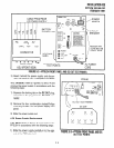
PDKWDDSS slots are identified and assigned in
Program
03 with special PCB code 64 (refer to
Figure 4-2).
I
PEKWDSS slots are identified and assigned in
Program
03 with special PCB codes 23 or 24
(refer to Figure 4-2).
DSS consoles and attendant telephones are
automatically assigned as DSSl/ATTl , DSS2/
ATT2, DSS3/ATT3, or DSS4/ATT4, starting with
the lowest DSSPEKU slots and continuing, in
consecutive order, to the highest DSSPEKU
slot (this also applies to DDSS consoles and
attendant telephones).
Each DSS console is assigned to the attendant
telephone connected to the same PEKU PCB
supporting that DSS console; however, DSS
consoles may be flexibly reassigned (in
Program
28) to any of the designated attendant tele-
phones
allowing a maximum of four DSS con-
soles assigned to one attendant telephone (this
also applies to digital telephones).
DSS console buttons may be flexibly assigned
(in
Program
29) as CO line buttons, DSS (hot
line) buttons, and speed dial buttons.
4.40 Data Interface Unit (DIU) Configuration
Notes
l
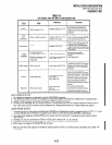
The integrated data interface unit (PDIU-DI)
shares the same wire pair and PDKU station
circuit with the digital telephone to which it is
connected. The PDIU-DI requires a PCTU3
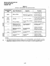
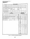
control PCB. The PDIU-DI capacity is shown in
Table 4-B.
l
The PDIU-DI is a DCE type device that normally
connects to a personal computer serial commu-
4-26