


INSTALLATION-SYSTEM DESCRIPTION
SECTION 200-096-202
FEBRUARY 1991
slots. These slots are labeled PCTU and SO1 w
S08; only the PCTU slot serves a dedicated func-
tion.
3.22 Each PCB slot (SO1 N S08) incorporates a
standard 40-pin female connector located in the
same vertical position on the KSU’s backplane.
This standardization enables any of the optional
PCBs to be installed in any slot. The PCTU slot
incorporates the same 40-pin female connector,
but it is set 0.25-inch higher, so that only a PCTU
PCB may be installed in the slot.
3.23 The power supply is factory-installed,
mounted horizontally above the PCB shelf, and is
secured with four combination slotted/Phillips
mounting screws.
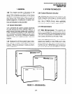
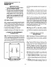
3.30 DK96 KSU Interior
3.31 The cabinet interior has two shelves (Figure
2-4). The top shelf has eight available PCB slots
labeled SO1 N S08. The bottom shelf has seven
available PCB slots labeled PCTU and SO9 N S14.
Only the PCTU slot serves a dedicated function.
3.32 Each PCB slot (SO1 w S14) incorporates a
standard 40-pin female connector located in the
same vertical position on the KSU’s backplane.
This standardization enables any of the optional
PCBs to be installed in any available slot. The
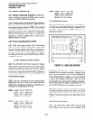
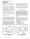
PPSU 24
080
@I
LG -24”, -24”z
@ CIRCUIT
FGOOd I BREAKERS
CONN---^- I iSGQ 3 l-l
BATTERY
FIGURE 2-5-DK24 POWER SUPPLY
FRONT PANEL
PCTU slot incorporates the same 40-pin female
connector, but it is set 0.25-inch higher, so that
only a PCTU PCB may be installed in the slot.
3.33 The power supply is factory-installed,
mounted vertically (to the right of the two PCB
shelves), and is secured with four combination
slotted/Phillips mounting screws.
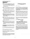
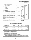
4 POWER SUPPLIES
4.00 STRATA DK systems incorporate single-
chassis, switching-type power supplies. The power
supplies for the three models are functionally iden-
tical (except for power capacity), although they
differ in appearance due to cabinet sizes and
mounting considerations. The DK24 model uses a
PPSU24 power supply (Figure 2-5), DK56 uses a
PPSU56 (Figure 2-6), and DK96 uses a PPSU96
(Figure 2-7).
4.01 The power supplies generate *5VDC and
-24VDC output voltages (that are protected by
mechanical circuit breakers located on the power
supply front panel). Input voltage is provided by a
standard 117VAC, 15 amp circuit. Electrical char-
acteristics include:
l
Primary Power
l
Input AC: 85VAC w 135VAC
l
AC Frequency: 50/60 Hz
l
Wattage: DK24/65, DK56/140,
DK96/230
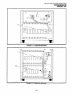
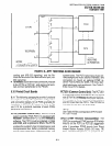
VOLTAGE LEDs
POWER SWITCH
\
AC INPUT
CIRCUIT
BREAKERS
BATTERY
CONNECTOR
FIGURE 2-6-DK56 POWER SUPPLY
FRONT PANEL
2-4