


INSTALLATION-PCB
SECTION 200-096-206
FEBRUARY1991
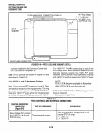
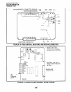
CO LINE MODULAR CO LINE MODULAR
CO LINE MODULAR CO LINE MODULAR
JACK CIRCUITS 1 AND 2 JACK CIRCUITS 1 AND 2
/JACK CIRCUITS 3 AND 4 JACK CIRCUITS 3 AND 4
BACKPLANE CONNECTOR BACKPLANE CON
1
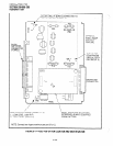
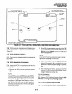
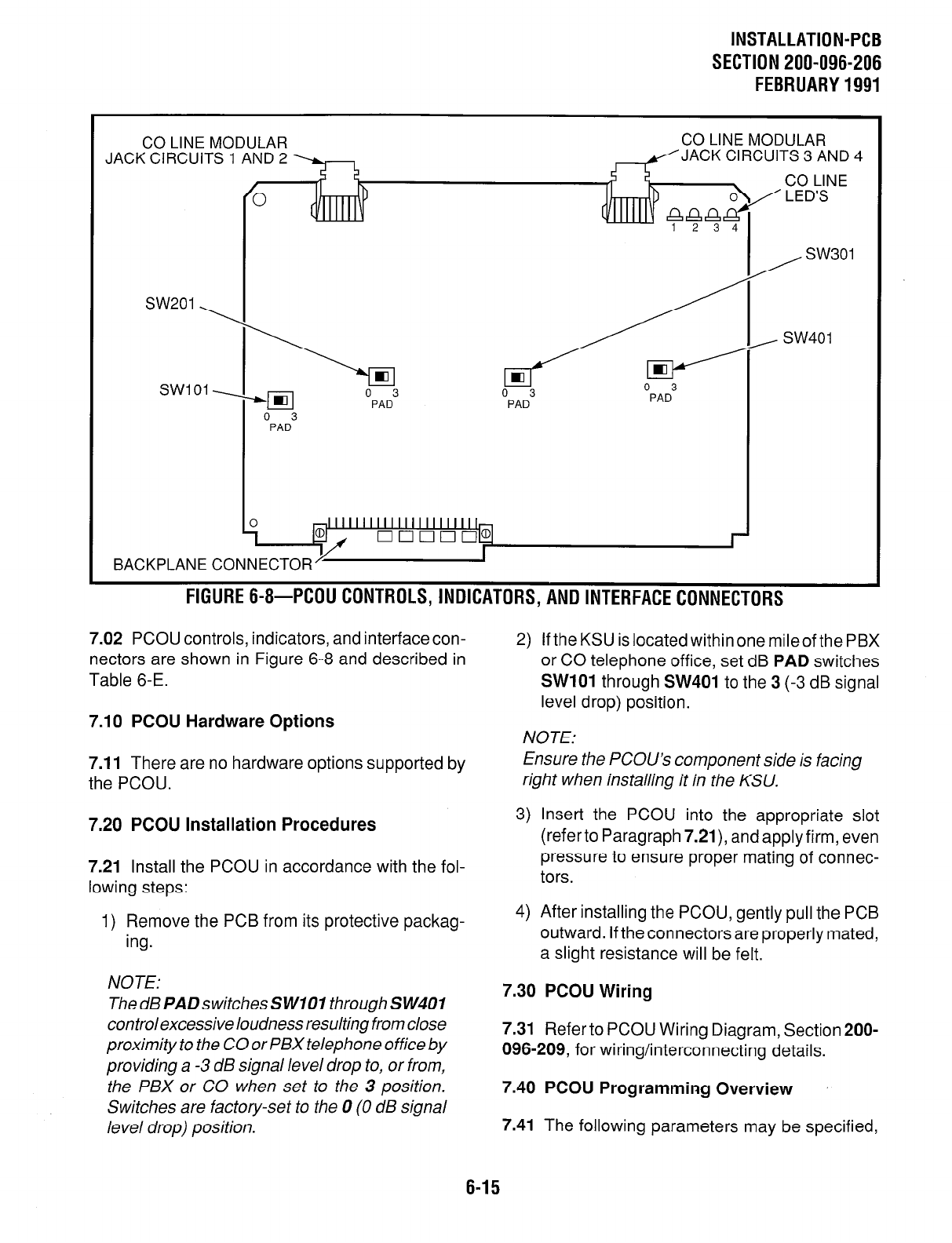
FIGURE 6-8-PCOUCONTROLS,INDICATORS,ANDlNTERFACECONNECTORS
7.02 PCOU controls, indicators, and interface con-
nectors are shown in Figure 6-8 and described in
Table 6-E.
7.10 PCOU Hardware Options
7.11
There are no hardware options supported by
the PCOU.
7.20 PCOU Installation Procedures
7.21 Install the PCOU in accordance with the fol-
lowing steps:
1) Remove the PCB from its protective packag-
ing.
NOTE:
ThedBPADswitchesSWlOl throughSW401
control excessive loudness resulting from close
proximity to the CO or PBX telephone office by
providing a -3 dB signal level drop to, or from,
the PBX or CO when set to the 3 position.
Switches are factory-set to the 0 (0 dB signal
level drop) position.
2) If the KSU is located within one mileof the PBX
or CO telephone office, set dB
PAD
switches
SW101
through
SW401
to the 3 (-3 dB signal
level drop) position.
NOTE:
Ensure the PCOU’s component side is facing
right when installing it in the KSU.
3) Insert the PCOU into the appropriate slot
(referto Paragraph 7.21), andapplyfirm, even
pressure to ensure proper mating of connec-
tors.
4) After installing the PCOU, gently pull the PCB
outward. If the connectors are properly mated,
a slight resistance will be felt.
7.30 PCOU Wiring
7.31
Refer to PCOU Wiring Diagram, Section 200-
096-209, for wiring/interconnecting details.
7.40 PCOU Programming Overview
7.41
The following parameters may be specified,
6-15