


INSTALLATION-SITE REQUIREMENTS
SECTION 200-096-203
FEBRUARY 1991
4 CABLE LENGTHS/NETWORK
REQUIREMENTS
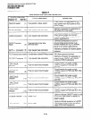
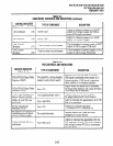
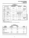
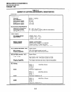
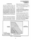
4.00 Table 3-A lists system loop requirements.
Table 3-B lists system network requirements. The
KSU must be located to allow compliance with the
specified requirements.
5 GROUNDING REQUIREMENTS
5.00 The system requires a solid earth ground for
proper operation. Failure to provide such a ground
may lead to confusing trouble symptoms and, in
extreme cases, system failure. The ground con-
nection is provided by the “third wire ground” from
the commercial power outlet.
NOTE:
The ground must be dedicated.
5.01 At most installations in the continental United
States, the ground provided by the “third wire
ground” at the commercial power outlet is satisfac-
tory for system requirements. However, in a small
percentage of installations, this ground may be
installed incorrectly. Before installing a system,
test the third wire ground for continuity by either
measuring the resistance between the third prong
terminal (earth ground) and a metal cold water
pipe (maximum: 5 ohms), or by using a commer-
cially available earth ground indicator.
5.02 If neither procedure is possible, perform the
earth ground test procedure in Paragraph
5.10.
I
NOTE:
See Paragraph 7 for more grounding re-
quiremen ts.
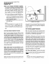
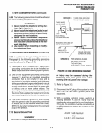
5.10 Earth Ground Test
WARNING!
Hazardous voltages that may cause death
or injury are exposed during the folio wing
test. Use great care when working with AC
power line voltage.
1) Obtain a suitable voltmeter, and set it for a
possible reading of up to 250 VAC.
2) Connect the meter probes between the two
main AC voltage terminals (white and black
wires) on the wall outlet. The reading obtained
should be between 100 - 120 VAC.
3) Move one of the meter probes to the third
terminal (green wire ground). Either the same
reading or a reading of zero volts should be
obtained.
4) If the reading is zero volts, leave one probe on
the ground terminal and move the other probe
to the second voltage terminal.
CAUTION!
If a reading of zero volts is obtained on
both voltage terminals (white wire to green
wire, black wire to green wire), the out/et is
not properly grounded. Omit steps 5 and
6, and proceed directly to step 7.
5) If a reading of zero volts on one terminal, and a
reading of 100 - 120 VAC on the other terminal
is obtained, remove both probes from the out-
let.
6) Set the meter to the “OHMS/Rx1 ” scale. Place
one probe on the ground terminal, and the other
probe on the terminal that produced a reading
of zero volts. The reading should be less than 1
ohm.
CAUTION!
If the reading is more than one ohm, then
the outlet is not adequately grounded.
7) If the above tests show the outlet is not properly
grounded, the condition should be corrected
(per Article 250 of the National Electrical Code)
by a qualified electrician before the system is
connected.
3-2