


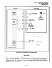

INSTALLATION-WIRING DIAGRAMS
SECTION 200-096-209
FEBRUARY 1991
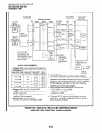
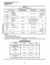
TABLE 9-B
STATION LOOP REQUIREMENTS
Device Description
PEKU
(ckts 1 - 8)
Electronic
P%JZ
telephone,
door phone/
control boxes
(ckts 5 - 8)
PEKU
(ckts 7 & 8)
DSS consoles
Max Loop Resistance
Max Distance from
(Including Device)
KSU to Device
40 ohms
1000 ft. (303 m)
20 ohms
500 ft. (152 m)
Number of
Wire Pairs 1
All need 2-pair.
EKTs which
receive OCA
calls need
3-pair.’
PSTU Standard
Approx. 3000 ft. (909 m)
(ckts 1 - 8) telephones, with 150 ohm device. See
P&U *
voice mail, 300 ohms
manufacturer’s product
auto attendant,
specifications for exact
(ckts 1 & 2)
etc. resistance of device.
PDKU
Digital
(ckts 1 - 8)
telephones
40 ohms
1000 ft. (303 m)
PDKU
(ckt 8)
DDSS consoles
40 ohms
1000 ft. (303 m)
PDKU
(ckts 1 - 7)
PDIU-DI 40 ohms
1000 ft. (303 m)
PDKU
(ckts 1 - 7)
PDIU-DS 40 ohms 1000 ft. (303 m)
NOTES:
1. Use 24 A WG twisted pairs.
2. PESU circuits 3 and 4 are not used.
3. Two-pair or larger wire is required to achieve maximum range, see table 9-D.
1 -pair
1 -pair
1 -pair
Shares digital
telephone
wire-pair?
1 -pair3
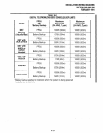
TABLE 9-C
NETWORK REQUIREMENTS
I
TOSHIBA TOSHIBA
Printed Circuit Board Printed Circuit Board
I
Pcou/Pcou2 Pcou/Pcou2
(Loop Start Line) (Loop Start Line)
PEMU PEMU
(Type I, TIE Line) (Type I, TIE Line)
2-wire 2-wire
4-wire 4-wire
PESU*/PSTU/PSTU2
(Off-premises
Station)
02LS2
RJ14C 0.2B
TLIlM
RJ2EX N/A
TL31 M
RJ2GX N/A
OL13A RJ21 X
N/A
I
*Circuits 1 and 2
Facility
Interface Code
Ringer
Equivalence
9-2