


INSTALLATION-SYSTEM DESCRIPTION
SECTION 200-096-202
FEBRUARY1991
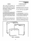
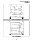
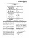
CO LINE
I
I I
PCOU
R I
R
I
I
I I
DPFT
T
T
oT
STANDARD
TELEPHONE
PSTU
R
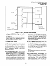
NOTES:
1. One of eight DPFT circuits.
2. Conditions of AC power on.
-24 VDC
INDICATING
AC POWER ON
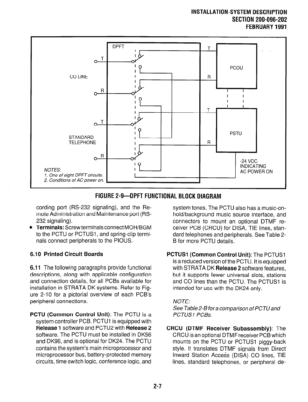
FlGURE2-9-DPFTFUNCTIONALBLOCKDIAGRAM
cording port (RS-232 signaling), and the Re-
mote Administration and Maintenance port (RS-
232 signaling).
l
Terminals:
Screwterminalsconnect MOH/BGM
to the PCTU or PCTUSI , and spring-clip termi-
nals connect peripherals to the PIOUS.
6.10 Printed Circuit Boards
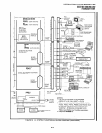
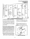
6.11 The following paragraphs provide functional
descriptions, along with applicable configuration
and connection details, for all PCBs available for
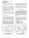
installation in STRATA DK systems. Refer to Fig-
ure 2-10 for a pictorial overview of each PCB’s
peripheral connections.
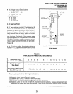
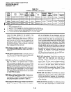
PCTU (Common Control Unit):
The PCTU is a
system controller PCB. PCTUl is equipped with
Release 1
software and PCTU2 with
Release 2
software. The PCTU must be installed in DK56
and DK96, and is optional for DK24. The PCTU
contains the system’s main microprocessor and
microprocessor bus, battery-protected memory
circuits, time switch logic, conference logic, and
system tones. The PCTU also has a music-on-
hold/background music source interface, and
connectors to mount an optional DTMF re-
ceiver PCB (CRCU) for DISA, TIE lines, stan-
dard telephones and peripherals. See Table 2-
B for more PCTU details.
PCTUSl (Common Control Unit):
The PCTUSI
is a reduced version of the PCTU. It is equipped
with STRATA DK
Release 2
software features,
but it supports fewer universal slots, stations
and CO lines than the PCTU. The PCTUSI is
intended for use with the DK24 only.
NOTE:
See Table 2-B for a comparison of PCTU and
PCTUSI PCBs.
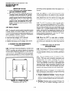
CRCU (DTMF Receiver Subassembly):
The
CRCU is an optional DTMF receiver PCB which
mounts on the PCTU or PCTUSI piggy-back
style. It translates DTMF signals from Direct
Inward Station Access (DISA) CO lines, TIE
lines, standard telephones, or peripheral de-
2-7