


INSTALLATION-CONFIGURATION
SECTION 200-096-204
FEBRUARY 1991
I
1 INTRODUCTION
1.01 STRATA DK systems are flexible in their
ability to meet varied system needs. A modular
building block approach allows the addition of vari-
ous parts to meet system needs and applications.
A universal slot concept is used in the KSU, which
means that a PCB slot in the KSU can accept any
one of a number of different PCBs. This is con-
trasted with a dedicated slot approach (used in
previous STRATA systems), where a particular slot
can only accept a specific PCB, such as a CO line
interface PCB. DK24 has six universal slots, DK56
has eight, and DK96 has 14. This increased flexibil-
ity in STRATA DK means that tradeoffs can be
made between the number of CO lines and stations
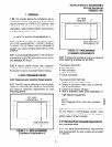
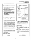
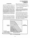
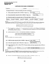
in a system application. This is illustrated in Figure
4-1.
1.02 Figure 4-l shows that in most configurations,
four CO lines can be traded for eight stations.
Conversely, for every eight stations that are given
up, four CO lines can be added. The maximum
quantities of 16 CO lines for DK24,20 CO lines for
DK56, and 36 CO lines for DK96 are based on
squared systems. Software allows 16 CG lines with
PCTUSl and 36 CO lines with PCTU (1, 2, or 3). 1
Similarly, the 24 station (PCTUSI) and 96 station
(PCTUI, 2, or 3) limits are software limitations.
I
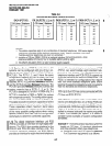
1.10 System Considerations
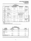
1.11 When no external options or TIE lines are
installed and only CO lines and station PCBs are
exchanged, the maximum configurations can be
summarized in Table 4-A.
1.12 Table 4-A shows the maximum number of
1 OOO-series digital telephone, 6500-series tele-
phones, and/or standard telephones that can exist
in each system. Due to power availability, the
numbers decrease if using 2000-, 3000-, 6000-, or
6005-series electronic telephones, a PEMU PCB,
or digital telephones with PDIU-Dls connected. I
When mixing different series telephones and/or if a
PEMU PCB is installed, use the Configuration
Guide, worksheet 7, to verify that the power sup-
plied is greater than the power used.
40
36
32
28
24
AVAILABLE
CO LINES
20
16
12
8
4
NOTES (DK24):
1. 24 stations are available 0
with PCTUSl -equipped DK24.
2. 32 stations are available
with PCTU-(1, 2, or 3) equipped
(WITHOUT
SYSTEM OPTIONS)
AVAILABLE STATION PORTS
DK24.
I
-_-__-- - . --- --~~~
FIGURE 4-l-PCB CONFIGURATION CHART
4-1