


INSTALLATION-WIRING DIAGRAMS
SECTION 200-096-209
FEBRUARY 1991
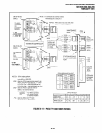
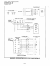
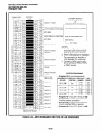
TO PEKU W/FEMALE
CONNECTOR
BRIDGING
LW-BR 1 29
h BR-Y I 19
BR-V 1 24
CIRCUIT 1 TO EKT
CUSTOMER SUPPLIED
TWO-WAY AMPLIFIER
OR
LINE REPEATERS (SEE NOTE 1)
PEKU, CIRCUIT 2 VOICE PAIR
PORT A (CENTRAL OFFICE SIDE)
NOT USED
PEKU, CIRCUIT 3 VOICE PAIR
PORT B (SUBSCRIBER SIDE)
NOT USED
(SEE NOTE 2)
TO 117VAC
CIRCUIT 4 TO EKT
NOTES:
CIRCUIT 5 TO EKT
OR HDCB
CIRCUIT 6 TO EKT
1. Amplifier or Repeater must have
Automatic Gain Control and be
FCC Registered from Port 68.
2. Refer to Manufacturer’s Installation
Documentation for Amplifier or
Line Repeater Pin numbering.
3. Connect to PEKU circuits only,
do not connect to PEW, PSTU,
CIRCUIT 7 TO EKT
OR DSS
or PDKU circuits.
CIRCUIT 8 TO EKT
OR DSS
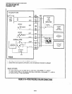
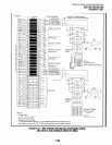
SYSTEM PROGRAMS
OCA Tl (OT)
OCA Rl (OR)
CIRCUIT 2
CIRCUIT 3
CIRCUIT 4
CIRCUIT 5
CIRCUIT 6
CIRCUIT 7
CIRCUIT 8
NOT USED
l
Program 10-3, circuit assignments:
PROGRAM 10-3 PEKU SLOT PEKU PORT PEKU
KEY/LED
POSITION NUMBER CIRCUIT
LED 01, ON
2nd
A = 09 CKT2
B=lO
CKT3
l
Program 10-1, key LED 19 and 20 ON.
l
Program 15-5, enable appropriate CO
lines for tandem connection.
l
Program 78-2, enable appropriate CO
lines if amplified DISA is required.
l
Program 10-2, key LED 18 and 19 ON.
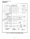
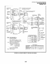
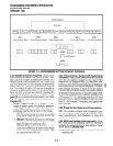
FIGURE 9-24-MDF WIRING/AMPLIFIED TWO-CO LINE CONFERENCE
9-26