


l
Wl
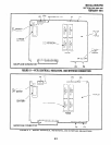
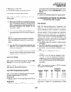
set to L (13OV P-P).
l
Two ringers maximum per port (H or L).
5.20 PSTU Installation Procedures
5.21
Install the PSTU in accordance with the fol-
lowing steps:
1) Remove the PCB from its protective packag-
ing. The protective shield on the back of the
PSTU is designed to protect the installer from
potentially hazardous ring voltage. Do not
remove this shield.
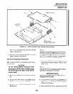
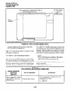
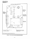
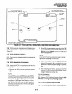
2) Ensure that the PSTU subunit (SSTU) is se-
curely attached to the PSTU (refer to Figure 6-
6).
NOTE:
Wl, the ring generator level option, should be
set in the H position (factory) for initial instal-
lation.
3) Insert the PSTU into the appropriate slot, and
apply firm, even pressure to ensure proper
mating of connectors.
4) After installing the PSTU, gently pull the PCB
outward. If the connectors are properly mated,
a slight resistance will be felt.
5.30 PSTU Wiring
5.31
Refer to PSTU Wiring Diagram, Section 200-
096-209, for wiring/interconnecting details.
5.32 The PSTU is registered for use with OLl3A
type lines for off-premises stations.
5.40 PSTU Programming Overview
5.41
The following parameters may be specified,
through programming, for the PSTU:
Program 03
l
Specify code 31 for all slots that have PSTUs
installed.
Program 31
l
Used to configure all PSTU ports connected to
INSTALLATION-PCB
SECTION 200-096-206
FEBRUARY 1991
Voice Mail or Auto Attendant devices (see Voice
Mail Installation, Section 200-096-208, for more
details).
.
Program 1 O-2
l
Used to set standard telephone ringing option.
6 STANDARD/ELECTRONIC TELEPHONE
INTERFACE UNIT (PESU)
6.00 General
6.01
The Standard/Electronic Telephone Unit
(PESU) provides two standard interface circuits (1
and 2) identical to PSTU circuits for connection
between standard telephones, or two wire devices,
and the system. It also provides four electronic
telephone interface circuits (5 N 8) identical to
PEKU circuitsforconnecting electronictelephones,
BGM, or one HDCB. The PESU provides a ring
generator for circuits 1 and 2 (with a ring voltage of
either 19OV P-P or 13OV P-P).
l
The PESU does not support a DSS console
connection.
l
The PESU provides connectors to mount the
EOCU for OCA to electronic telephones.
l
The PESU supports HDCB and BGM connec-
tion.
l
PESU Requires
Release
2 software.
NOTE:
A CRCU (-4 or -8) must be installed on the
PCTU or PCTUS 1 for the system to recognize
DTMF tones sent from standard telephones or
other two-wire devices that are connected to
the PEW.
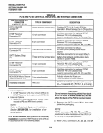
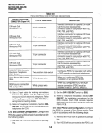
6.02 The maximum number of PESUs allowed
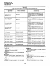
per system is shown below:
Electronic
System PESUs Std Telephone PCTU
DK24 3
6 12
w
DK24 5 10 20 (1 or2)
DK56 8 16 32 (1 or2)
DK96 12 24
48
(1 or2)
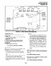
6.03 The PESU controlsand interface connectors
are shown in Figure 6-7 and described in Table
6-D.
6-11