


INSTALLATION-PERIPHERALS
SECTION 200-096-208
FEBRUARY1991
telephones and 1 OOO-series digital telephones
equipped with HHEU PCBs (refer to Section 200-
096-207). The HESB automatically turns off once
the ringing call or voice first has been manually
answered from the electronic or digital telephone.
This turn-off feature prevents audio feedback prob-
lems.
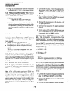
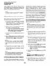
5.02 Amplified Speaker Option. The Amplified
Speaker option allows the HESB to be configured
as a paging speaker. The HESB is connected to the
PIOU, PIOUS, or PEPU 600-ohm page output to
provide an amplified external speaker.
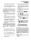
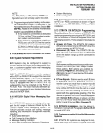
5.03 Talkback Amplified Speaker Option. The
Talkback Amplified Speaker option allows a talkback
speaker to be provided in areas where a telephone
is not needed, such as in conjunction with a door
phone. In this configuration, the HESB is connected
to the PIOU, PIOUS, or PEPU 6OOQ (duplex) output
and is used as the amplifier and speaker. The door
phone unit (MDFB) is connected to the HESB, and
serves as a microphone to provide talkback opera-
tion (the MDFB pushbutton is inoperative, and the
unit serves only as a microphone for talkback).
NOTE:
The PIOU, PIOUS, and PEPU 600 Q (duplex)
page output is compatible with most commer-
cially available talkback amplifiers.
5.10 System Hardware Requirements
5.11 System hardware requirements vary de-
pending on the HESB option selected. Refer to the
following installation procedures for the system
hardware requirements for each option.
5.20 HESB Option Installation
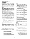
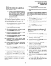
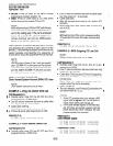
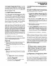
5.21 Loud Ringing Bell Installation. Install the
HESB Loud Ringing Bell option in accordance with
the following steps (refer to Figure 8-l 1 for elec-
tronic or 8-l 1 A for digital telephones).
1) Connect a jumper between terminals 6 and 7
on the HESB TBI terminal block.
2) Connect a jumper between terminals 5 and 8
on the HESB TBI terminal block.
3) Connect a jumper between terminals 4 and 5
on the HESB TB2 terminal block.
NOTES:
1.
2.
4)
5)
6)
7)
8)
9)
t
t
t
t
HESB connections made in steps 4 N 7
may be accomplished using the HESB
VOICE modular jack instead of the TBI
terminal block.
Install an HHEU PCB and HESC-65 cable
in the 6500-series electronic telephone
per Section 200-096-207 before pro-
ceeding with steps 4 and 5.
Connect terminal 1 of the HESB TBI terminal
Ilock to the red (+) wire of the HESC-65 cable
Jsing a modular block per Figure 8-l 1.
Connect terminal 2 of the HESB TBI terminal
slack to the green (-) wire of the HESC-65
:able using a modular block per Figure 8-l 1.
Connect terminal 3 of the HESB TBI terminal
Ilock to pin 3 of the electronic telephone’s
nodular block (VOICE-TIP).
Connect terminal 4 of the HESB TBI terminal
Yock to pin 4 of the electronic telephone’s
nodular block (VOICE-RING).
Connect the HACU-120 power supply’s +12V
ead to terminal 1 of the HESB TB2 terminal
Ilock, and connect the power supply’s OV lead
0 terminal 2.
Plug the provided power cord into the power
supply and to a 117VAC, 60Hz power source.
NOTE:
See Figure 8-24 for HESB wall mounting
instructions.
5.22 Loud Ringing Bell Test. Test the Loud Ring-
ing Bell installation in accordance with the following
steps:
1)
2)
3)
Make a CO or station call to the station config-
ured for the loud ringing bell.
l
Ringing will be heard over the HESB.
Adjust the HESBvolume control to the desired
level.
If ringing is heard at the station, but not over
the HESB, perform the following check while
the station is ringing:
a) Using a suitable voltmeter, measure volt-
age across terminals 1 (+) and 2 (-) of the
HESB TBI terminal block.
l
Voltage indication should be 4.5 N
5.0 VDC.
8-8