


INSTALLATION-PCB
SECTION 200-096-206
FEBRUARY1991
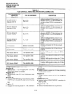
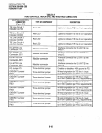
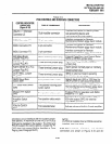
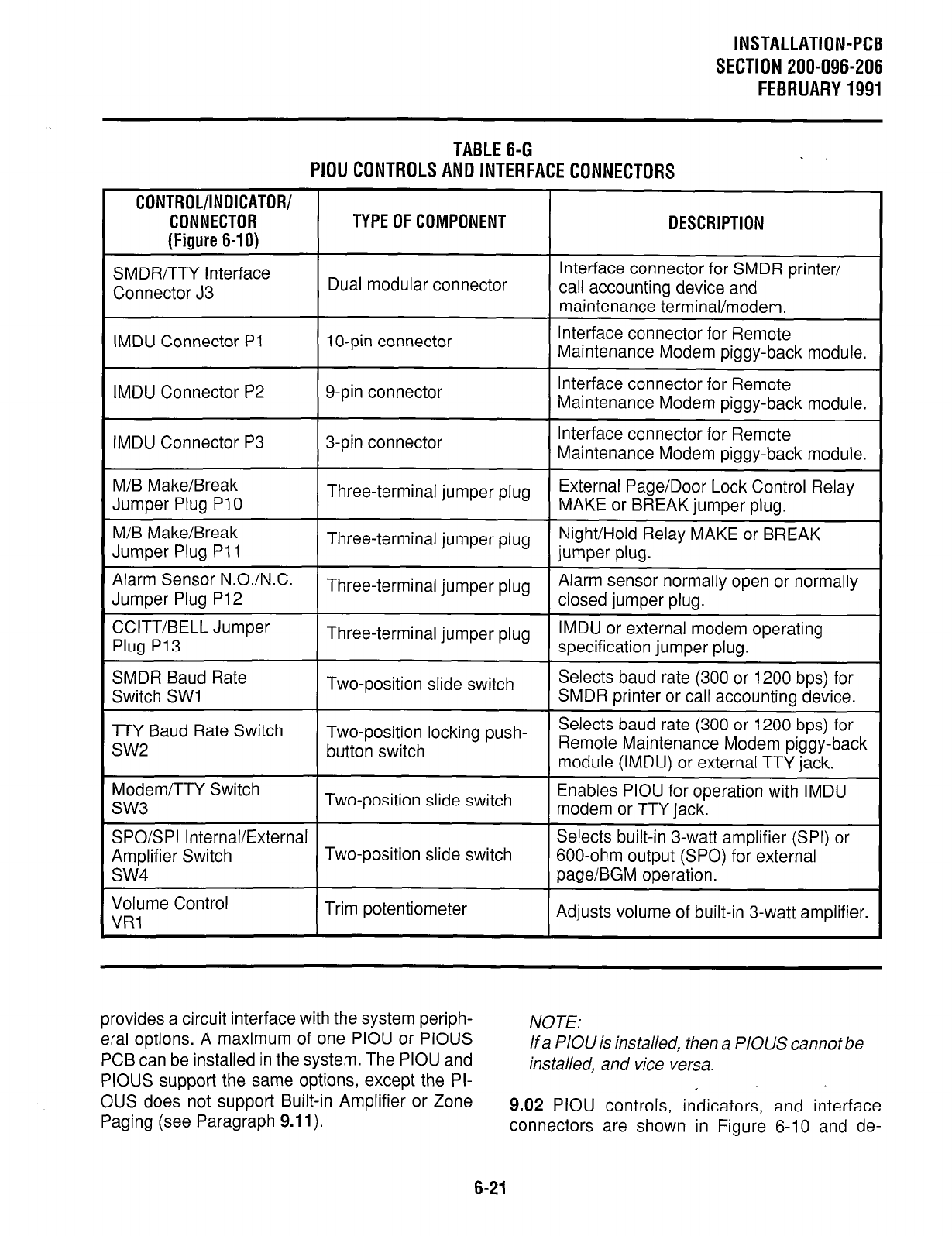
TABLE6-G
PIOU
CONTROLSANDINTERFACECONNECTORS
.
CONTROL/INDICATOR/
CONNECTOR
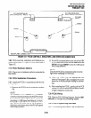
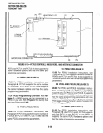
(Figure 6-I 0)
TYPE OF COMPONENT
DESCRIPTION
SMDR/TTY Interface
Connector J3
Dual modular connector
IMDU Connector PI 1 O-pin connector
Interface connector for SMDR printer/
call accounting device and
maintenance terminal/modem.
Interface connector for Remote
Maintenance Modem piggy-back module.
IMDU Connector P2 g-pin connector
Interface connector for Remote
Maintenance Modem piggy-back module.
IMDU Connector P3
3-pin connector
Interface connector for Remote
Maintenance Modem piggy-back module.
M/B Make/Break
Jumper Plug PI 0
M/B Make/Break
Jumper Plug PI 1
Three-terminal jumper plug
External Page/Door Lock Control Relay
MAKE or BREAK jumper plug.
Three-terminal jumper plug
Night/Hold Relay MAKE or BREAK
jumper plug.
Alarm Sensor N.O./N.C.
Three-terminal jumper plug
Alarm sensor normally open or normally
Jumper Plug P12 closed jumper pluo.
CCITT/BELL Jumper
Plug P13
SMDR Baud Rate
Switch SW1
Three-terminal jumper plug
IMDU or external modem operating
specification jumper plug.
Two-position slide switch
Selects baud rate (300 or 1200 bps) for
SMDR printer or call accounting device.
TTY Baud Rate Switch
SW2
Two-position locking push-
Selects baud rate (300 or 1200 bps) for
button switch
Remote Maintenance Modem piggy-back
module (IMDU) or external TTY iack.
Modem/TTY Switch
SW3
I
Two-position slide switch
Enables PIOU for operation with IMDU
modem or TTY jack.
SPO/SPI Internal/External
Selects built-in 3-watt amplifier (SPI) or
Amplifier Switch
Two-position slide switch
600-ohm output (SPO) for external
SW4
page/BGM operation.
Volume Control
VRl
Trim potentiometer
Adjusts volume of built-in 3-watt amplifier.
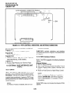
provides a circuit interface with the system periph-
eral options. A maximum of one PIOU or PIOUS
PCB can be installed in the system. The PIOU and
PIOUS support the same options, except the PI-
OUS does not support Built-in Amplifier or Zone
Paging (see Paragraph
9.11).
NOTE:
If a PIOU is installed, then a PIOUS cannot be
installed, and vice versa.
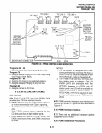
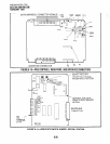
9.02 PIOU controls, indicators, and interface
connectors are shown in Figure 6-10 and de-
6-21