


INSTALLATION-WIRING DIAGRAMS
SECTION 200-096-209
FEBRUARY1991
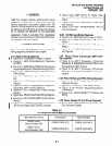
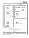
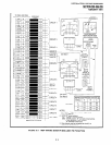
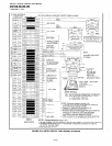
TO PEKU OR PESU
W/FEMALE CONNECTOR BR’DG’NG
/-I InP
66M150 SPLIT BLOCK ’
CIRCUIT 5
CIRCUIT 6
CIRCUIT 7
CIRCUIT 8
NOT USED
SCREW
1654321 u
uuun I
I l”lYL n
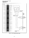
MDFB (REAR VIEW)
( , ; 4 , / lDOO$--1
I
VR
VT
MDFB
DOOR
PHONE B
OR DOOR
LOCK
CONTROL
I I
I
See Note I l
J
See Note 2
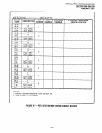
1 MDFB (DOOR PHONE) STATION #s
See Note 3
NOTES:
26
1
161
1
162
1
163
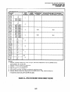
1. On PEKU or PESU, cut W9. See Programs 39,
77-I. 77-2, and 79.
2. HDCB “B” output options:
SWI: Always in DOOR position.
SW2: DOOR position; “B” connects to door phone.
LOCK (Release 2 only) position;
“B” connects to door lock.
3. Door phones may be connected to circuit 5 on
ports 4, 12,20 and 28 only.
I
FlGURE9-3-MOFWIRING-DOOR PHONE/LOCKTO PEKU/PESU
9-5