


INSTALLATION-TELEPHONE
SECTION 200-096-207
FEBRUARY1991
telephones, standard telephones, DSS consoles,
and door phones/locks to STRATA DK systems.
The following paragraphs provide general require-
ments for telephone installation.
3.01 Refer to the Programming Procedures, Sec-
tion 200-096-300, for programming requirements
and procedures.
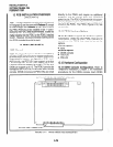
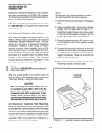
3.10 Electronic Telephone Connections
3.11
Electronic telephones are connected to the
PEKU or PESU PCB (via the MDF) with standard
twisted-pair jacketed telephone cable. Two-pair
wiring, as a minimum, is required for telephone
connection. However, 3-pair wiring is recom-
mended to permit future upgrades, such as Off-
hook Call Announce. To accommodate the elec-
tronic telephone line cord, the cable should be
terminated in a modular station connector block
(RJ-25) at the station location. The standard
modular electronic telephone cord length is 7 feet
(the maximum allowed length is 25 feet).
I
NOTE:
See Section 200-096-209 for secondarypro-
tector information.
3.12 The overall length of the station cable run
from the KSU to the telephone must not exceed
1,000 feet (305 M), if using 24 AWG cable.
CAUTION!
When installing the station cable, do not
run parallel to and with@ 3 feet of an AC
power line. AC power lines should be
crossed at right (90”) angles only. In par-
ticular, avoid running station wire pairs
near devices thatgenerate electricalnoise,
such as neon or fluorescent Iigh t fixtures.
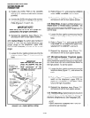
3.13 Electronic Telephone Wall Mounting.
Electronic telephones may be mounted on a wall
or any other flat, vertical surface to which the base
can besecured. When selecting the mounting site,
consider the electronic telephone’s weight and the
additional stresses to which the mounting will be
subjected. Wall mount electronic telephones in
accordance with the following steps:
7-4
NOTE:
All electronic and digital telephone models
are wall mounted in the same manner:
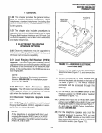
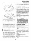
1) Remove the base as described in Paragraph
2.11.
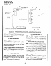
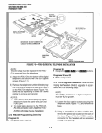
2) Using a suitable cutter, remove the handset
hanger from the base (refer to Figure 7-l).
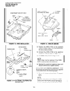
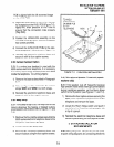
Insert the handset hanger in the slot provided
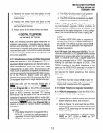
on the front of the telephone (Figure 7-6).The
hanger fits in the notch on the handset.
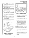
3) Rotate the telephone base 180” and secure it
to the telephone with its four captive screws
(Figure 7-7).
4) Connect the electronic telephone to the wall
modular connector with a cord approximately
four inches long (available at most telephone
supply companies). Route the cord into the
hollow portion of the base.
5) Mount the electronic telephone on the wall
mounting modular connector plate.
HANDSET
HANGER
\
FlGURE7-6-HANDSETHANGERINSTALLATION '