


INSTALLATION-SYSTEM DESCRIPTION
SECTION 200-096-202
FEBRUARY 1991
NOTE:
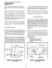
As of November 1989, the PSTU is equipped
with a jumperplug to change the ring genera-
tor no load output from 79OV peak-to-peak
square wave (high) to 130V peak-to-peak
square wave (low). The low setting is used
with peripherals that are sensitive to high-ring
voltage (almost all peripherals function with
high-ring voltage).
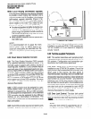
7 SYSTEM CONTROLS AND INDICATORS
7.00 System controls and indicators are located
inside the KSU. Controls and indicators may be
accessed only by removing the cabinet’s front
cover. Controls and indicators are located on the
power supply, KSU chassis, and on various PCBs.
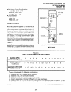
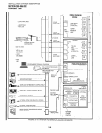
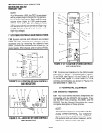
FIGURE 2-ll-LOCATION OF DK24 CONTROLS
AND INDICATORS
8 9 10
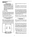
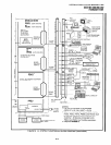
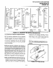
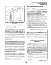
FIGURE 2-12-LOCATION OF DK56 CONTROLS
AND INDICATORS
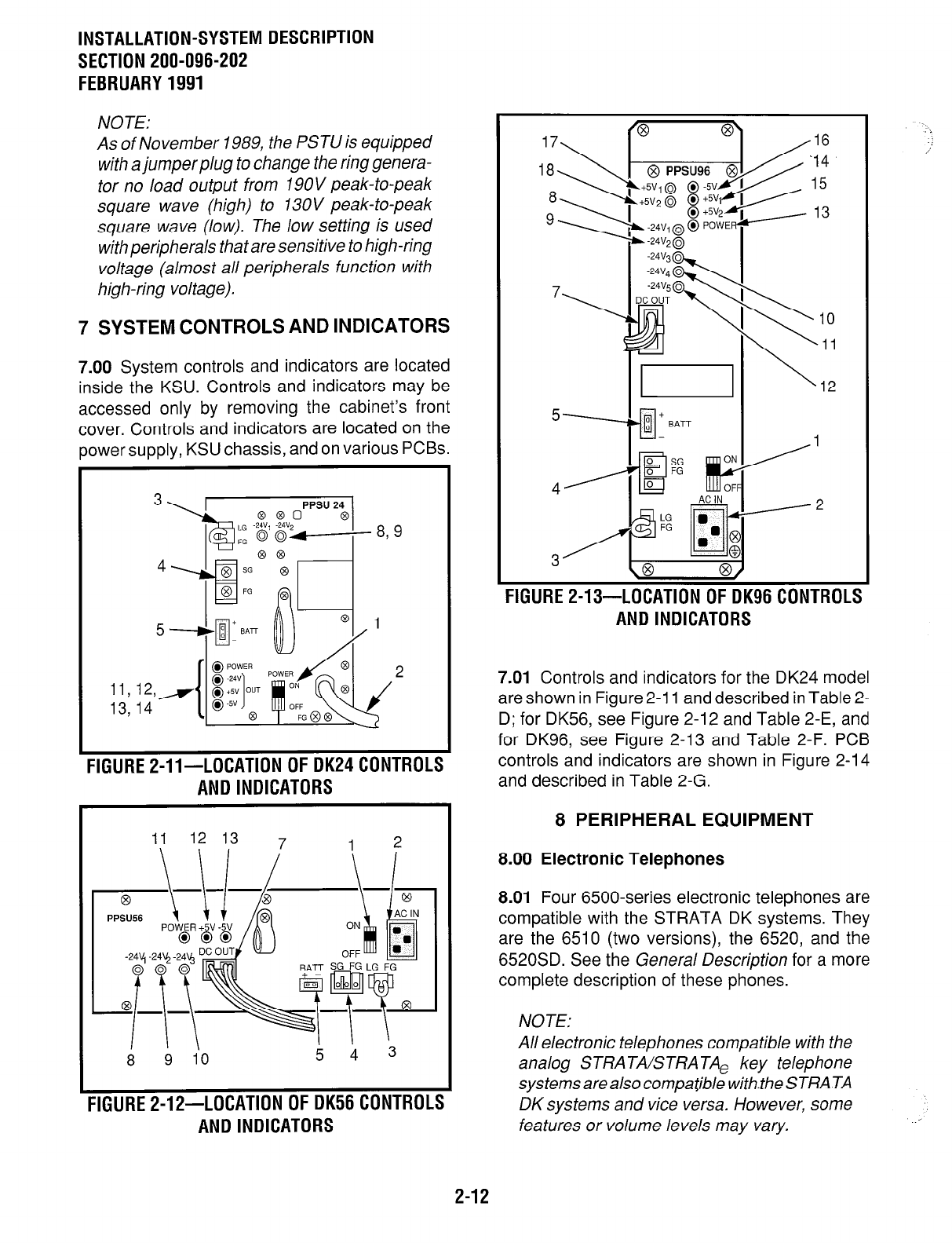
FIGURE 2-13-LOCATION OF DK96 CONTROLS
AND INDICATORS
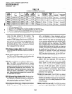
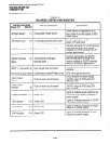
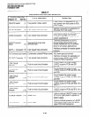
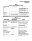
7.01 Controls and indicators for the DK24 model
are shown in Figure 2-11 and described in Table 2-
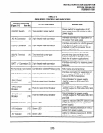
D; for DK56, see Figure 2-12 and Table 2-E, and
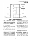
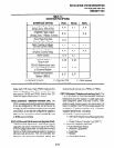
for DK96, see Figure 2-13 and Table 2-F. PCB
controls and indicators are shown in Figure 2-14
and described in Table 2-G.
8 PERIPHERAL EQUIPMENT
8.00 Electronic Telephones
8.01 Four 6500-series electronic telephones are
compatible with the STRATA DK systems. They
are the 6510 (two versions), the 6520, and the
6520SD. See the Genera/ Description for a more
complete description of these phones.
NOTE:
All electronic telephones compatible with the
analog STRA TA/STRA TAe key telephone
systems are also compatible withlhe STRATA
DK systems and vice versa. However, some
features or volume levels may vary.
2-12