


INSTALLATION-PERIPHERALS
SECTION 200-096-208
FEBRUARY1991
l
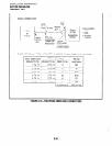
Request to Send (RTS, Pin
4): Some DTE de-
vices send an RTS signal (EIA circuit CA) to the
DCE devicewhen they are ready to transmit data
on the TD lead. If the DTE device does not
generate the RTS signal, the DIU DIP switch
SWI-4
should be set ON to inform the DIU.
Sometimes, the DTE/DCE device may use RTS/
CTS for Ready/Busy type flow control, in these
cases DIP switch
SWI-4
should be OFF (see
Figure 8-26 for DIP switch information).
l
Clear to Send (CTS, Pin 5):
The DCE device
sends the CTS signal (EIA circuit CB) which
indicates that it is prepared to transmit data to the
line side. The DCE device sends this signal only
when it receives the RTS signal from the DTE
device. Sometimes, the DTE/DCE device may
use RTS/CTS for Ready/Busy type flow control;
in these cases, dip switch
SWI-4
should be OFF
(see Figure 8-26 for DIP switch information).
l
Data Set Ready (DSR, Pin
6): When connected
to the communication channel and prepared to
exchange control characters to initiate data
transmission, the DCE device sends the DSR
signal (EIA circuit CC) to the DTE device. If the
PDIU DIP switch
SWI-2
is set ON, DSR will be
ON continuously; if the switch is set OFF, DSR
follows DTR (if DSR is ON, DTR is ON, etc.)
SW1
-2 should be OFF in most cases (see Figure
8-26 for DIP switch information).
l
Data Carrier Detect (DCD, Pin 8):
The DCE
device sends the DCD signal (DCD, Pin 8) when
receiving the carrier signal on the line side.
Before transmitting or receiving data, most DTE
devices require that the DCD be ON. If the carrier
signal is removed by the remote end or lost due
to a fault condition on the line, the DCE notifies
the DTE device by an OFF condition with the
DCD signal; PDIU DIP switch
SWI-2
is set ON to
set the DCD ON continuously; if set OFF, the
DCD signal will only be ON when connection
between two DlUs is established and OFF when
aconnection is not established.
SWI-2
isset OFF
when the DTE/DCE uses the DTR/DSR signals
for Ready/Busy flow control (see Figure 8-26 for
DIP switch information).
l
Data Terminal Ready (DTR, Pin
20): The DTE
device sends the DTR signal (EIA circuit CD) to
the DCE device, prompting the DCE device to
open the communication line. The line is closed
and the call disconnected when the DTE device
quits sending the DTR signal. DTR may be sent
any time to indicate that the DTE is ready to
transmitorreceivedata.DIPswitchSWl-ishould
be set OFF in most cases (see Figure 8-26 for
DIP switch information).
l
Ring Indicator (RI, Pin
22): The RI signal (EIA
circuit CE) is sent by the DCE device to the DTE
device. Whenever the DCE device receives a
ringing signal on the line side, it turns the RI
signal ON. If DIU DIP switch
SWI-3
is set ON,
the RI signal will be on continuously if ringing; if
the switch is set OFF, the RI signal will be one
second ON/three seconds OFF when the DIU
detects ringing signal.
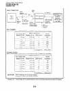
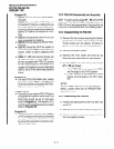
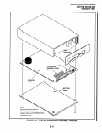
12.30 DIP Switch Options
12.31
The PDIU-DI and the PDIU-DS each have a
four-control DIP switch which can be configured for
signaling options. The switch is located on the
bottom of the PDIU-DI, and on the back panel of the
PDIU-DS (see Figure 8-26).
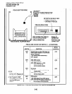
l SWI-1
: Normally this switch is set ON to discon-
nect devices from DlUs automatically. The con-
nection is maintained if data is exchanged be-
tween the device and the DIU within eight to nine
second intervals. If
SWI-1
is OFF on the called
and calling DIU, data calls will remain connected
until released manually.
IMPORTANT NOTE!
SWl-1 ON, auto disconnect, is in effect
only for D/Us that have AT commands
enabled in Program 20 (LED 02 ON).
l
SWI-2:
This switch is placed in the ON position
when the PDIU-DI (or PDIU-DS configured like a
DCE) must hold DCD and DSR ON continu-
ously. If
SWI-2
is OFF, DSR follows DTR and
DCD will be ON only when the DIU is connected
on a data call to another DIU.
SWI-2
should be
OFF on a DIU when it is connected to a personal
computer that uses a communications software
program to establish data calls with AT com-
mands.
l
SWI-3:The PDIU-DI (or PDIU-DSconfiguredas
a DCE) sends the Ring Indicate (RI) signal to the
computer to tell the computer (DTE) that the
PDIU isreceivinganincomingcall.SWl-3should
be ON for the DIU to send RI steady, and OFF to
send at one second ON/three seconds OFF in-
tervals.
8-40