


console requires dedicated use of circuit 8 of a
particular PDKU PCB.
13.14 PDIU-DS Configuration.
Refer to Periph-
erals Installation, Chapter 8, for installation proce-
dures for the PDIU-DS. A PDIU-DS can be con-
nected to circuits 1 N 7 on a PDKU; the circuit must
be dedicated to the PDIU-DS.
13.15 PDIU-DI Configuration.
Refer to Telephone
Installation, Chapter 7, and Peripherals Installation,
Chapter 8, for installation procedures for the PDIU-
DI. PDIU-Dls can be equipped with any digital tele-
phone connected to PDKU circuits 1 N 7, but the
quantity is limited (see Table 4-B in Chapter 4).
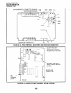
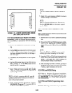
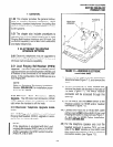
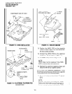
13.20 PDKU Installation Procedures
13.21
Install the PDKU in accordance with the
following steps:
1) Remove the PCB from its protective packag-
ing.
2) Insert the PDKU into the appropriate slot, and
apply firm, even pressure to ensure proper
mating of connectors.
NOTE:
Ensure the PDKU’s component side is facing
right when installing it in the KSU.
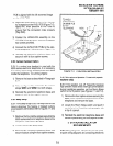
4) After installing the PDKU, gently pull the PCB
outward. If the connectors are properly mated,
a slight resistance will be felt.
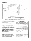
13.30 PDKU Wiring
13.31
Refer to PDKU Wiring Diagrams, Chapter 9,
for wiring/interconnecting details.
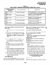
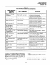
13.40 PDKU Programming Overview
13.41
The following parameters may be specified,
through programming, for the PDKU:
Program 03
l
Specify code 62 to indicate a station line PDKU.
e Specify code 64 to indicate a PDKU configured
for a DDSS console.
INSTALLATION-PCB
SECTION 200-096-206
FEBRUARY 1991
Programs 20,21, and 22
l
Use to configure PDIU-Dls and PDIU-DSs.
Programs 28 and 29
.
l
Use for DDSS assignments.
Program 30
l
Adjusts initial off-hook volume level for digital
telephone handsets.
Program 92-5
l
Initializes initial ringing, speaker, and muted ring
volume levels of digital telephones.
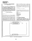
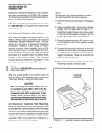
14 PCTU (RELEASE 3)
14.01
For PCTU3 (Figure 6-15) installation in-
structions, see Paragraph 3. The PCTU3 PCB has
the same station and CO line capacity and per-
formsthesamefunction as the PCTUl and PCTU2:
It provides centralized control for the KSU. PCTU3
is intended for use with DK56 and DK96; it can also
be used with DK24.
NOTE:
The PI jumper, which is on the PCTU 1 and 2,
is not on the PCTU3. Its function is automatic
with PCTU3 (see Table 6-A).
15 PEKU (RELEASE 3)
15.00 For PEKU installation instructions, see
Paragraph 4. PCTU3 supports the same number of
PEKUs, electronic telephones, and options as
PCTUl and PCTU2.
15.01 Alternate Background Music (BGM)
Configuration.
With
Release3,
a BGM source can
be connected to a PEKU in any slot. With
Program
19,
identify the slot. Adhere to all other steps in
Paragraph 4.15.
15.02 External Amplifier Connection.
With
Re-
lease
3, a customer-supplied two way external
amplifier may be connected to PEKU ports. With
Program 1
O-3, identify these ports. See Chapter 8
for amplifier installation information.
16 PSTU (RELEASE 3)
16.00 For PSTU installation instructions, see
Paragraph 5. PCTU3 supports the same number of
6-27