


INSTALLATION-SYSTEM DESCRIPTION
SECTION 200-096-202
FEBRUARY 1991
2.20 Stored Programming
2.21 System Operating Software.
System op-
erating software is stored in ROM, and is revised
only by Toshiba software engineers.
2.22 Configuration and Custom Programming.
Each system’s individual configuration and cus-
tom programming is stored in RAM. The contents
of system RAM is user-developed and -pro-
grammed based on the system’s configuration
and the user’s requirements. System RAM is pro-
tected by a lithium battery with a shelf life of
approximately six years.
2.30 Pulse Code Modulation (PCM)
2.31
PCM technology allows fully non-blocking
intercom and outside line talk paths. Talk paths
operate through digital switching, as opposed to
analog crosspoints. Analog-to-digital and digital-
to-analog conversion is accomplished by CODEC
integrated circuits.
3 KEY SERVICE UNITS (KSU)
3.01 The STRATA DK KSUs consist of single,
free-standing cabinets that can be configured for
either wall or table-top mounting. One-inch rubber
feet on the base of the cabinet ensure that proper
clearance is maintained when the KSU is table-top
mounted. The KSU interior houses the PCBshelves
and the power supply.
3.02 External dimensions and approximate
weights for the DK24, DK56, and DK96 models are
listed below. Weights are based on cabinets con-
taining a full complement of PCBs.
DK24
Height: 10.6 in. (269 mm)
Width: 16.0 in. (406 mm)
Depth: 9.0 in. (229 mm)
Weight: 19.4 Ibs (9 kg)
DK56
Height: 15.0 in. (381 mm)
Width: 16.0 in. (406 mm)
Depth: 9.0 in. (229 mm)
Weight: 37.5 Ibs (17 kg)
DK96
Height: 18.6 in. (475 mm)
Width: 19.6 in. (500 mm)
Depth: 9.0 in. (229 mm)
Weight: 55.1 Ibs (25 kg)
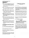
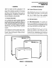
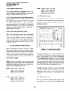
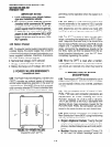
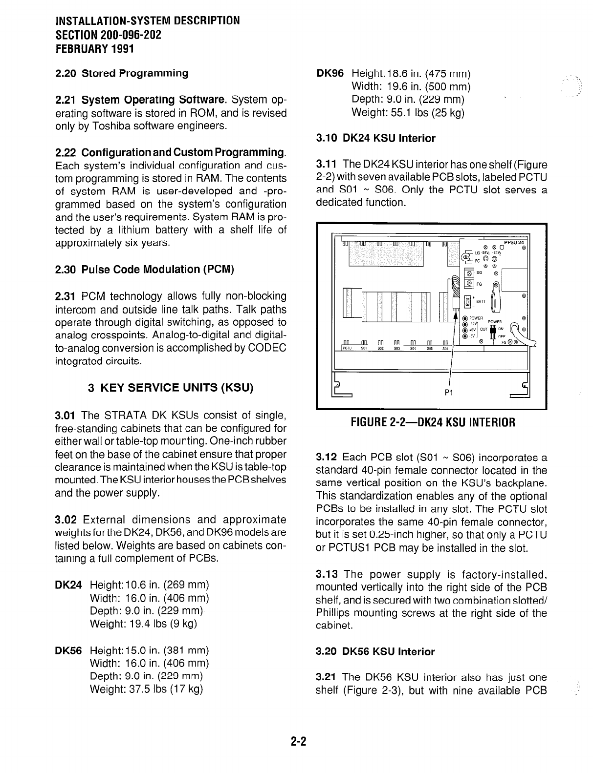
3.10 DK24 KSU Interior
3.11
The DK24 KSU interior has one shelf (Figure
2-2) with seven available PCB slots, labeled PCTU
and SO1 w S06. Only the PCTU slot serves a
dedicated function.
FIGURE 2-2-DK24 KSU INTERIOR
3.12 Each PCB slot (SO1 N S06) incorporates a
standard 40-pin female connector located in the
same vertical position on the KSU’s backplane.
This standardization enables any of the optional
PCBs to be installed in any slot. The PCTU slot
incorporates the same 40-pin female connector,
but it is set 0.25-inch higher, so that only a PCTU
or PCTUSl PCB may be installed in the slot.
3.13 The power supply is factory-installed,
mounted vertically into the right side of the PCB
shelf, and is secured with two combination slotted/
Phillips mounting screws at the right side of the
cabinet.
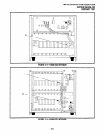
3.20 DK56 KSU interior
3.21 The DK56 KSU interior also has just one
shelf (Figure 2-3), but with nine available PCB
2-2