


INSTALLATION-SYSTEM DESCRIPTION
SECTION 200-096-202
FEBRUARY1991
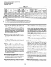
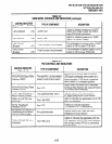
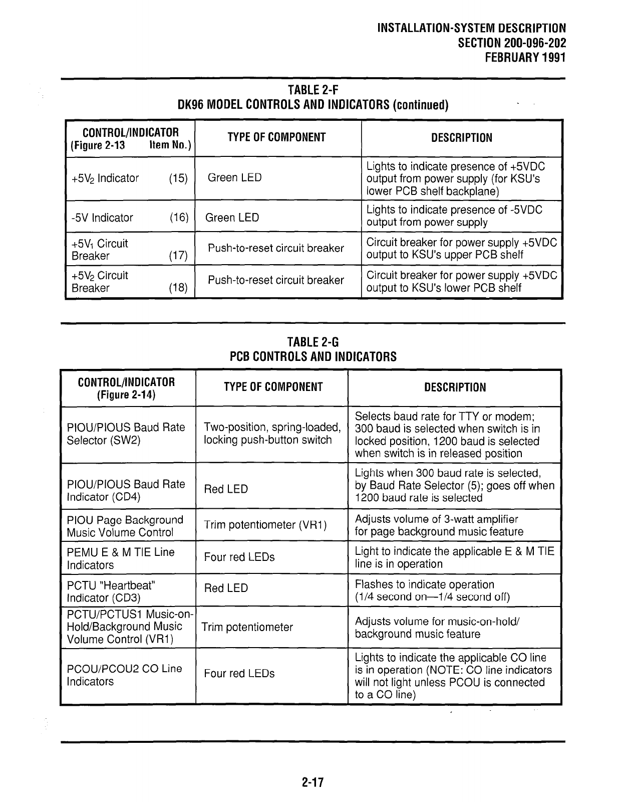
TABLE2-F
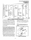
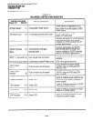
DK96MODELCONTROLSANDlNDlCATORS(continued)
.
CONTROL/lNOlCATOR
(Figure 2-13
Item No.)
TYPE OF COMPONENT DESCRIPTION
Lights to indicate presence of +5VDC
+5V2 Indicator
(15)
Green LED output from power supply (for KSU’s
lower PCB shelf backplane)
-5V Indicator
(16) Green LED
Lights to indicate presence of -5VDC
output from power supply
+5V1 Circuit
Breaker
-45V2 Circuit
Breaker
Push-to-reset circuit breaker
Circuit breaker for power supply +5VDC
(17)
output to KSU’s upper PCB shelf
Push-to-reset circuit breaker
Circuit breaker for power supply +5VDC
(18)
output to KSU’s lower PCB shelf
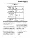
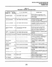
TABLE2-G
PCBCONTROLSANDINDICATORS
CONTROL/INDICATOR
(Figure 2-14)
TYPE OF COMPONENT DESCRIPTION
Selects baud rate for TTY or modem;
PIOU/PIOUS Baud Rate
Two-position, spring-loaded,
300 baud is selected when switch is in
Selector (SW2)
locking push-button switch
locked position, 1200 baud is selected
when switch is in released position
Lights when 300 baud rate is selected,
PIOU/PIOUS Baud Rate
Indicator (CD4)
Red LED
by Baud Rate Selector (5); goes off when
1200 baud rate is selected
PIOU Page Background
Trim potentiometer (VRI)
Adjusts volume of 3-watt amplifier
Music Volume Control
for page background music feature
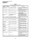
PEMU E & M TIE Line
Four red LEDs
Light to indicate the applicable E & M TIE
Indicators
line is in operation
PCTU “Heartbeat”
Red LED
Flashes to indicate operation
Indicator (CD3)
(l/4 second on-l/4 second off)
PCTU/PCTUSI Music-on-
Hold/Background Music Trim potentiometer
Adjusts volume for music-on-hold/
Volume Control (VRI)
background music feature
PCOU/PCOU2 CO Line
Indicators
Four red LEDs
Lights to indicate the applicable CO line
is in operation (NOTE: CO line indicators
will not light unless PCOU is connected
to a CO line)
2-17