


PROGRAMMINGPROCEDURES-INSTRUCTIONS/SYSTEMRECORDS
SECTION 200-096-302
FEBRUARY1991
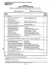
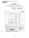
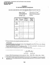
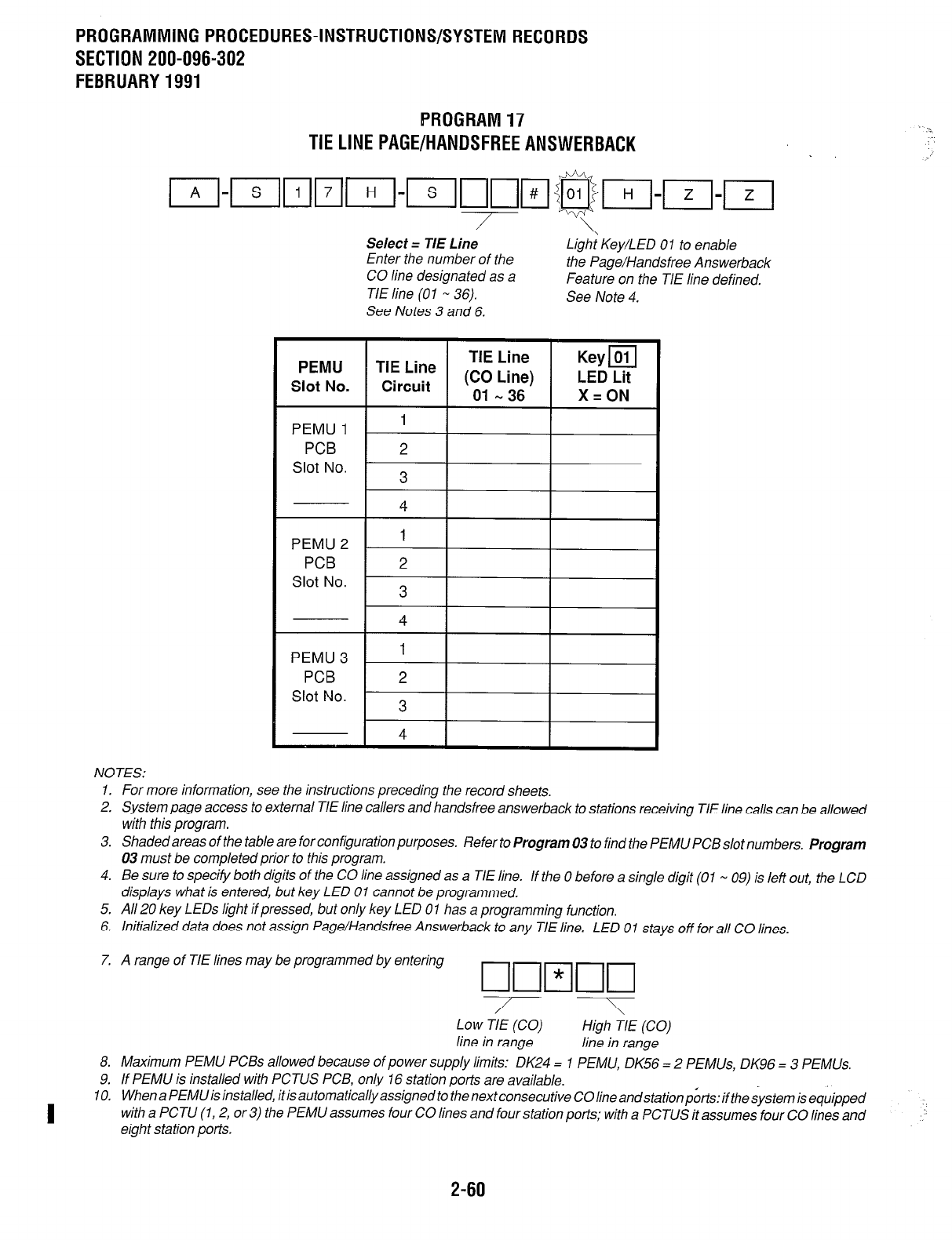
PROGRAM17
TIELlNEPAGE/HANDSFREEANSWERBACK
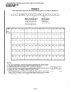
I,-,In~p-j-~~p@&T-j-~-p-j
/
Select = TIE Line 2 Key/LED 01 to enable
Enter the number of the
the Page/Handsfree Answerback
CO line designated as a
Feature on the TIE line defined.
TIE line (01 - 36).
See Note 4.
See Notes 3 and 6.
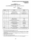
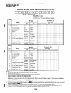
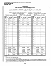
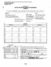
I -~~ 1
me
ine)
36
Keym
LED Lit
X=ON
I
PEMU 1
I
I I
PCB 2
I
PEMU 2
PCB
Slot No.
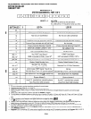
NOTES:
1. For more information, see the instructions preceding the record sheets.
2. System page access to external TIE line callers and handsfree answerback to stations receiving TIE line calls can be allowed
with this program.
3. Shadedareas of the table are for configuration purposes.
Refer to Program 03 to find the PEMU PCB slot numbers. Program
03 must be completed prior to this program.
4. Be sure to specify both digits of the CO line assigned as a TIE line.
If the 0 before a single digit (01 - 09) is left out, the LCD
displays what is entered, but key LED 01 cannot be programmed.
5, All 20 key LEDs light if pressed, but only key LED 0 1 has a programming function.
6. Initialized data does not assign Page/Handsfree Answerback to any TIE line.
LED 01 stays off for all CO lines.
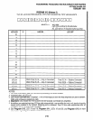
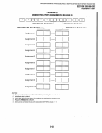
7. A range of TIE lines may be programmed by entering
/
Low TIE (CO)
High TIE (CO)
line in range line in range
8. Maximum PEMU PCBs allowed because of power supply limits: DK24 = 1 PEMU, DK56 = 2 PEMUs, DK96 = 3 PEMUs.
9. If PEMU is installed with PCTUS PCB, only 16 station ports are available.
IO.
I
When a PEMU is installed, it is automatically assigned to the next consecutive CO line andstation
p&s:
if the system is
quipped
with a PCTU (1,2, or 3) the PEMU assumes four CO lines and four station ports; with a PCTUS it assumes four CC lines and
eight station ports.
2-60