


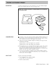

CONSIDERATIONS
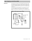
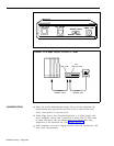
● Processor Module. The Processor Module, which contains the
microprocessor that controls the system’s programs and features, always
occupies the next slot (slot 0) on the control unit. This module may also
contain jacks for optional equipment.
A red light on this module goes on
when the system is powered up.
If the light goes on at any other time, it
indicates a problem with the system.
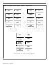
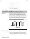
● Circuit Pack Modules. The Circuit Pack Modules can occupy slots 1
through 5 on the basic carrier and slots 6 through 11 on an expansion
carrier.
The modules are interchangeable during installation, except for
slot 1 on the basic carrier, which must have either a 4-Line/8-Analog Voice
Terminal (408) Module or an 8-Analog Voice Terminal (008) Module.
There are four types of Circuit Pack Modules.
A 4-Line/8-Analog Voice Terminal {408) Module has jacks for four
outside lines and eight analog voice terminals.
An 8-Analog Voice Terminal (008) Module has jacks for eight analog
voice terminals.
An 8-Digital Station (008D) Module has jacks for eight digital voice
terminals.
A 4-Line (400 with TTR) Module with Touch-Tone Receivers has
jacks for four lines and four Touch-Tone receivers.
An 8-Line (800) Module has jacks for eight lines.
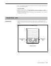
A 12-Basic Telephone (012) Module has jacks for 12 basic telephones.
(For more information about this type of module, see “Basic Telephone
Module. ” )
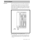
Labels on the Circuit Pack Modules identify the station jacks by intercom
number and the line jacks by line number. Each jack is accessed through a
cutout in the front of the housing.
●
●
●
At some point, you may need to change modules in the control unit. If
you replace a module with one of a different type, you must readminister
the system to reassign numbers to lines and stations. (For the procedure
see “System Renumbering. ” ) Keep in mind that changing station modules
may require readministration of features that are unique to analog or
digital voice terminals.
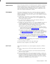
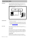
On each Circuit Pack Module is a Power Failure Telephone Jack to which
the administrator can connect a basic telephone. When there is a power
failure, the Power Failure Telephone automatically turns on and connects
to the first line on the module. (See “Power Failure Telephone.”)
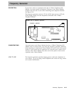
If you have a 12-Basic-Telephone (012) Module in either type of carrier,
you must connect a frequency generator to the Power Module located in
the first slot. For more information, see “Frequency Generator. ”
If you replace a module in your control unit with one of a different type, you
need to renumber the lines and stations in your system. Follow the
procedure under
“System Renumbering. ”
2-176 Accessory Equipment