Installing and cross-connecting a Power Fail Transfer Unit Page 443 of 466
Communication Server 1000E Installation and Commissioning
Installing and connecting a third-party PFTU
Follow the equipment manufacturer’s instructions for installing the PFTU.
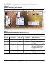
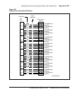
Use the information in Table 59 to connect a third-party PFTU.
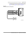
Note 1: Refer to Figure 180 on page 440 to see where the Auxiliary
cable connects to the CS 1000E system.
Note 2: If power is removed from the QUA6, a transfer of the PFTU can
occur.
Table 59
PFTU control lead signals
Lead State
NTAK1104 AUX
cable lead
When PFTU is in
non-transferred state
When PFTU is in
transferred state
BRTN GROUND GROUND
BRTN GROUND GROUND
-48V AUX -48V DC (250 mA max.) -48V DC (250 mA max.)
PFTS OPEN GROUND


