


Page 108 of 466 Installing and connecting CS 1000E hardware
NN43041-310 Standard 01.11 October 2008
port of the call server, while the CT connects to the TLAN port of the call
server. The 1E and 2T ports must be attached to the layer 2 switch.
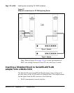
MGC Ethernet Capabilities
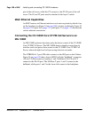
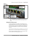
An MGC features six Ethernet interfaces set to auto-negotiate by default: four
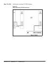
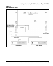
on the faceplate (see Figure 24 on page 109), and two on the back. Figure 25
on page 110, Figure 26 on page 111, and Figure 27 on page 112 illustrate the
various ethernet connections.
Connecting the CS 1000E Core CP PM Call Servers to an
MG 1000E
An MG 1000E performs functions under the direct control of the CS 1000E
Core CP PM Call Server. The MG 1000E detects stimulus events from its
interface cards and passes these events to the CS 1000E Core CP PM Call
Server, where the high-level call processing decisions are made.
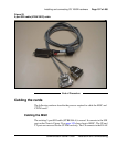
The NTBK48AA 3-port SDI cable connects to the SDI port on the Cabinet.
Figure 24 on page 109 shows front of MGC with the "bulkhead" connectors
(1E and 2T) that connect to numbers 1 and 2 bulkhead. The CE and CT
connect to the ELAN port. The 100 Base T ports 1 and 2 connect to the
bulkhead, while ports 1 and 2 in the lower left connect to the backplane.