


Page 184 of 466 Installing a Signaling Server
NN43041-310 Standard 01.11 October 2008
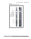
— Insert the end of a longer RJ-45 CAT5 Ethernet cable (not
supplied) into the ELAN network interface port (ELAN port) on
the faceplate of the server
— Insert the other end of the RJ-45 CAT5 Ethernet cable into an
Ethernet port on the ELAN Ethernet switch
2 Connect the Signaling Server to the TLAN subnet.
• if the Call Server is not connected to the Media Gateway Controller
(MGC)
— Insert the end of one of the 25-cm RJ-45 CAT5 Ethernet cables
shipped with the server (NTDU0606E6) into the TLAN network
interface port (TLAN port) on the faceplate of the server
— Insert the other end of the 25-cm RJ-45 CAT5 Ethernet cable
into the MGC TLAN Ethernet port
• if the Call Server is connected to the MGC
— Insert the end of a longer RJ-45 CAT5 Ethernet cable (not
supplied) into the TLAN network interface port (TLAN port) on
the faceplate of the server
— Insert the other end of the RJ-45 CAT5 Ethernet cable into an
Ethernet port on the TLAN Ethernet switch
End of Procedure
Note: If the Call Server is connected to the Media Gateway Controller,
you can not use the 25-cm CAT5 Ethernet cables shipped with the
Signaling Server (NTDU0606E6). You must obtain CAT5 Ethernet
cables that are long enough to connect the Signaling Server directly to the
ELAN and TLAN Ethernet switches from the faceplate ELAN and
TLAN Ethernet ports.
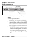
Complete Procedure 40 to connect a Nortel CP PM Signaling Server (model
NTDW66AAE5) to the ELAN and TLAN subnets of a CS 1000M system.
IMPORTANT!
Connecting a Nortel CP PM Signaling Server to the ELAN and TLAN
subnets of a CS 1000M system causes a service disruption.