


Page 104 of 466 Installing and connecting CS 1000E hardware
NN43041-310 Standard 01.11 October 2008
information, see Communication Server 1000: System Redundancy
(NN43001-507).
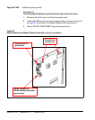
Procedure 10
Connecting Campus Redundant CP PM Call Servers
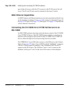
1 Connect the CAT5E RJ-45 LAN 2 port of Call Server 0 to a 100BaseT
ELAN network interface on the local Baystack 470-24T switch.
2 Connect the CAT5E RJ-45 LAN 2 port of Call Server 1 to a 100BaseT port
on the remote Baystack 470-24T switch.
3 Link the two Baystack 470-24T switches with two high-speed single-mode
fiber uplinks (1 Gbps per link), using the built-in GBIC ports for dedicated
uplink connectivity.
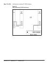
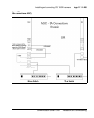
4 Assign three VLANs to the BayStack 470-24T ports.
• VLAN 1 – Default
— All 104 ports belong to the four BayStack 470-24T ports.
• VLAN 2 – HSP
— Two ports connect CP PM packs HSP ports in Call Server 0 and
Call Server 1.
— Four high-speed fiber uplinks (GBIC ports)
• VLAN 3 – ELAN
— Includes 2 ELAN network interfaces on the CP PM Call Servers,
for example, for ELAN connections for ISP1100 Signaling
Servers, MG 1000Es, Call Pilot, Symposium, OTM, Element
Manager.
— Four high-speed fiber uplinks (GBIC ports)
End of Procedure
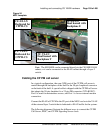
Installing the cards
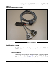
Installing a DSP Daughterboard
The following procedure describes how to install a DSP Daughterboard on an
MGC card: