


Page 282 of 466 Configuring a terminal and SDI ports
NN43041-310 Standard 01.11 October 2008
• Parity - none
• Flow control - none
The baudrate setting can be changed in Overlay 17, however changing this
setting is not recommended since it will only used when SL1 is loaded.
Note that only the Port 0 serial port displays the boot sequence from BIOS,
Bootrom & OS before the call server application is started. Port 1 will only
start displaying output when call server application is started (Sysload
Phase1).
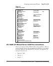
MG 1000E SDI connection
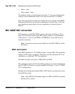
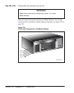
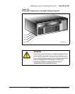
SDI connection to the MG 1000E is made at the back. See Figure 122 on
page 284 for location of the 9-pin DTE (male) connector. It is modified to
isolate pins 6, 7, and 8. Use PORT0 of NTBK48AA 3-port SDI cable for
terminal connection.
Note: Connection must be made initially to each MG 1000E to set the
IP address.
MGC serial ports
Each MGC installed in a CS 1000E provides 3 remote SDIs. The maximum
number of TTYs does not change. Therefore, once the maximum TTYs are
configured, no additional TTYs are supported.
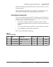
The MGC has three serial ports: SDI0, SDI1 and SDI2.
The serial ports can be used for local debug purposes or can be configured in
the CS 1000E Call Server as system terminals in Overlay 17 (see 4.3.1 MGC
TTY Configuration).
During initial configuration either SDI0 or SDI1 must be connected to access
the installation menu.
Note: Only SDI0 has full modem support, as SDI1 and SDI2 do not have
hardware flow control.