


Page 350 of 466 Installing the Main Distribution Frame
NN43041-310 Standard 01.11 October 2008
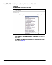
Terminal block requirements
The cross-connect terminal requires enough connecting blocks to terminate
up to four 25 pair cables for each Media Gateway and each Media Gateway
Expander. When Ethernet connections are used instead of traditional cabling,
the Media Card Input/Output adapter is used:
• For the 1.5 Mbit DTI/PRI circuit card NTRB21, use the NTBK04 cable.
• For the 2.0 Mbit DTI circuit card NTAK10, 2.0 Mbit PRI circuit card
NTAK79, and 2.0 Mbit PRI circuit card NTBK50, use the NTBK05
cable.
• Each IPE card slot equipped with a Line or Trunk card requires a 25-pair
cable from the host Media Gateway or Media Gateway Expander.
• Four conductors for the AUX cable from the Media Gateway.
• One 25-pair cable from each Power Fail Transfer Unit (PFTU) QUA6.
• Wiring from telephones and trunks
Installing a BIX cross-connect terminal
Procedure 80 describes how to install a BIX cross-connect terminal. For
detailed information, refer to the Nordex BIX documentation.
Procedure 80
Installing a BIX cross-connect terminal
1 Refer to the equipment layout plan to determine where to place the
cross-connect terminal.
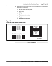
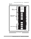
2 Lay out the terminal blocks as shown in Figure 150 on page 351.
DANGER
Do not install telephone wiring during a lightning storm.
Never touch uninsulated telephone wiring, unless the
line is disconnected at the network interface.