Installing the Main Distribution Frame Page 359 of 466
Communication Server 1000E Installation and Commissioning
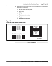
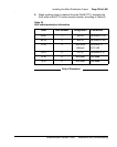
8 When auxiliary power is required from the QUA6 PFTU, terminate the
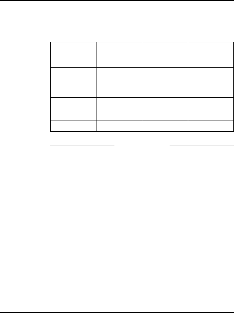
AUX cable at the PFTU cross-connect terminal, according to Table 45.
End of Procedure
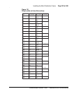
Table 45
AUX cable termination information
Color Wire number Designation Connection
W-BL 1 BRTN to QUA6-J1 1R
BL-W 2 BRTN to QUA6-J1 2R
O-W 3 -48V AUX
(250mA)
to QUA6-J1
25T, 25R
W-O 4 PFTS to QUA6-J1 2T
G-W 5 Not used Not used
W-G 6 Not used Not used


