


Page 190 of 466 Installing a Signaling Server
NN43041-310 Standard 01.11 October 2008
Installing the software
To install software and enter basic system configuration parameters on an
IBM X306m or HP DL320-G4 Signaling Server, complete Procedure 43.
Procedure 43
Installing Signaling Server software
Upon completion of Step 1, this procedure takes approximately 45 minutes to
complete.
1 From your Planning and Engineering group, obtain the following network
and IP Telephony data for this Signaling Server:
• node ID for the IP Telephony node
• node IP address for the IP Telephony node
• hostname for the Signaling Server
• ELAN network interface IP address, Subnet mask, and Gateway
• TLAN network interface IP address, Subnet mask, and Gateway
• ELAN network interface IP address of the Call Server
• Primary and Alternate NRS IP addresses for this networked system.
Refer toIP Peer Networking: Installation and Commissioning
(NN43001-313)
• NRS role, if applicable. Refer to IP Peer Networking: Installation and
Commissioning (NN43001-313)
2 Boot the Signaling Server from the Removable Media Device (RMD):
• For IBM X306m, HP DL320-G4, or Nortel ISP1100 Signaling
Servers, insert the CS 1000 Release 5.0 Signaling Server Software
CD into the CD drive and press the RST button on the front panel of
the Signaling Server to trigger a cold boot. This forces the Signaling
Server to boot from the CD.
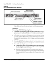
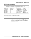
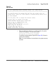
• For a Nortel CP PM Signaling Server, insert the CS 1000 Release 5.0
Signaling Server Software CF card into the faceplate CF drive and
press the RST button on the faceplate of the Signaling Server to
trigger a cold boot. The CP PM System BIOS Configuration screen
appears (see Figure 61) with an instruction to press F to force the
Signaling Server to boot from the CF card.