


Page 102 of 466 Installing and connecting CS 1000E hardware
NN43041-310 Standard 01.11 October 2008
• Procedure 10: "Connecting Campus Redundant CP PM Call Servers"
on page 104
• Procedure 11: "Installing a DSP Daughterboard" on page 105
• Procedure 12: "Installing the MGC card" on page 105
• Procedure 13: "Installing the CP PM card" on page 106
• Procedure 14: "Inserting a Shielded 50-pin to Serial/ELAN/TLAN
adapter" on page 113
• Procedure 15: "Connecting a Media Card to the ELAN subnet"
on page 114
• Procedure 16: "Connecting a Media Card to the TLAN subnet"
on page 115
• Procedure 17: "Connecting a Media Gateway to a Media Gateway
Expansion" on page 115.
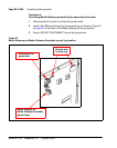
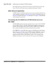
Connecting CP PM Call Server 0 to CP PM Call Server 1
The CS 1000E redundant architecture allows for the separation of
Call Server 0 and Call Server 1. The two processors are connected by either
a direct 100BaseT crossover cable or a carefully engineered Layer 2/VLAN
infrastructure.
Campus Redundancy provides the ability to separate the CS 1000E CP PM
Call Servers in a campus environment for “campus mirroring”. This feature
enables two CP PM Call Servers, one active and one redundant, to be
connected through an Ethernet network interface. Campus Redundancy can
operate using any vendor’s Layer 2 switching products, in addition to the
BayStack 470. The distance depends upon network parameter limitations
specified in Communication Server 1000: System Redundancy
(NN43001-507).
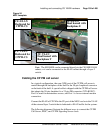
To separate the redundant CP PM Call Servers, the ELAN subnet and the
subnet of the High Speed Pipe (HSP) can be extended between the two
processors with an Ethernet switch, using Layer 2 protocol.
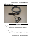
If the two CP PM Call Servers are collocated, they can be connected using a
standard CAT5e or CAT6 crossover cable, limited to 100 meters in length.