


Installing and connecting CS 1000E hardware Page 103 of 466
Communication Server 1000E Installation and Commissioning
For detailed information on Campus Redundancy, refer to Communication
Server 1000: System Redundancy (NN43001-507).
The Layer 2 switch allows the ELAN subnet and the subnet of the High Speed
Pipe (HSP) to be extended between the two processors. The
BayStack 470-24T provides full duplex wire-speed 100BaseT with no
significant packet loss (less than 0.001%) and delays of less than 100 usec.
The method used to connect CP PM Call Server 0 to CP PM Call Server 1
depends on the proximity of the units. If the units are co-located, follow
Procedure 9 to connect the CP PM Call Servers. If the units are configured for
Campus Redundancy, follow Procedure 10 to connect the CP PM Call
Servers.
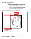
Connecting co-located CP PM Call Servers
Follow Procedure 9 to connect co-located CP PM Call Servers.
Procedure 9
Connecting co-located CP PM Call Servers
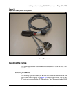
1 Plug one end of the CAT5E RJ-45 crossover cable (NTRC17) into the
LAN 2 connector on the front of Call Server 0.
2 Plug the other end of the CAT5E RJ-45 NTRC17 crossover cable into the
LAN 2 connector on the front of Call Server 1.
End of Procedure
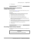
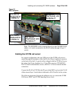
Connecting Campus Redundant CP PM Call Servers
The MultiLink Trunking (MLT) feature of the BayStack 470-24T enables the
two uplink fiber ports to be grouped but is not solely necessary for the two
uplink fiber ports to be linked. Grouping the uplink fiber ports increases
aggregate throughput up to 2 Gbps between sides with active redundant links.
The port-based VLANs used in the BayStack 470-24T switches operate in
accordance with the IEEE 802.1Q tagging rules. VLAN ports are grouped
into broadcast domains by assigning them to the same VLAN. Frames
received in one VLAN can be forwarded only within that VLAN. For more