


Installing a Signaling Server Page 213 of 466
Communication Server 1000E Installation and Commissioning
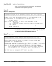
16 Enter <CR> or y to confirm the parameters.
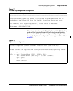
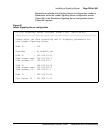
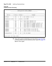
The example in Figure 87 on page 212 is for a Leader Signaling Server
configured with an Alternate H.323 and SIP NRS. The confirmation
screens for a Follower and stand-alone Signaling Server are similar,
showing the same list of parameters, specifically:
• The configuration screen for the Follower Signaling Server displays
only the value for the Hostname parameter; all other values are
blank.
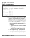
• The configuration screen for the stand-alone Signaling Server
displays values for the Hostname, ELAN network interface, TLAN
network interface, and NRS parameters. The Node ID field is set to
0. The Call Server IP field is set to 0.0.0.0.
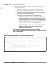
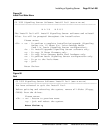
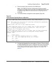
After you confirm the IP configuration, the following system messages
appear:
For future reference, the ELAN MAC address is:
“00:02:b3:c5:5l:c6”.
Wrote config file "/u/config/bootp.tab".
Wrote config file "/boot/nvram.sys".
Wrote config file "/u/config/config.ini".
Wrote config file "/u/config/nrsconf.xml".
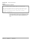
Note: You must configure the ELAN network interface MAC address for
the newly installed Signaling Server in the Element Manager node
configuration web page.
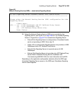
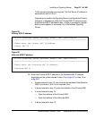
17 To complete the installation, the Installation Status Summary screen
appears as shown in Figure 88 on page 214.