


Page 388 of 466 Installing Line cards and cross-connecting telephones
NN43041-310 Standard 01.11 October 2008
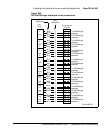
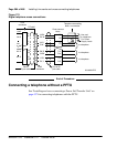
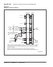
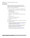
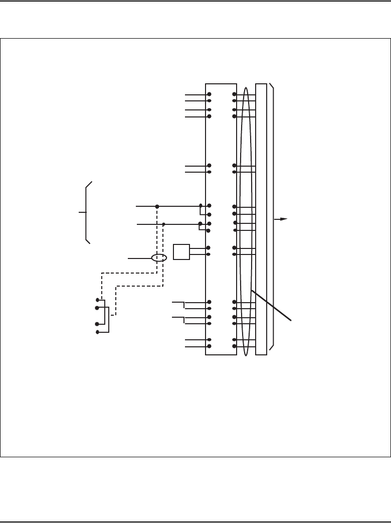
Figure 172
Attendant console connections
Cross-connect
block
W-BL
BL-W
W-O
O-W
Y-BL
BL-Y
V-S
S-V
W-S
S-W
R-O
To 1st TN
To 2nd TN
To 3rd TN
Y-
O
O-
Y
+VP
S
+VPS RTN
Relay 2
Relay 1
ASM/
ADN
R-G
G-R
+ AU
X
- AUX
To +15 AUX
(W-G 1 dot wire)
on AUX cable
To -15 AUX
(G-W 1 dot wire)
on AUX cable
Console power
from AUX
cable
(one console
only)
Note:
As an alternative, console
power can be obtained from the
4 th and 5 th TNs on the circuit
card.
To 4th TN Tip
To 4th TN Rin
g
Console
connecto
r
Cable to
M2250
Console
26
1
27
2
30
5
32
7
33
8
41
16
42
17
50
25
Cable from
console to
cross-connect
terminal
To 5 th TN Tip
To 5 th TN Ring
O-
R
BK-BL
BL-BK
36
11
GND
TC
Note 1:
The M2250 is powered using the line circuits and if required from the AUX cable. In addition to
the primary TN, secondary TN and ASMTN, two TNs are for power from the AUX cable are cabled to
the M2250 through the + AUX and - AUX leads. Maximum loop length is 3000 ft (915 m) of 24 AWG
(5.0 Metric Wire Gauge).
Note 2:
When additional options are used (BLF), an additional 16V DC power supply is
required. The 16V DC source is cabled through +VPS and +VPS RTN leads. The maximum
distance from the console to the power source is 120 ft (36 m) of 24 AWG (5.0 Metric Wire Gauge) wire.
(Note 1)
(Note 2)
553-8352.EPS