


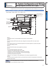

2-51
1
Before Using the Products
2
Preparation
3
Connection
4
Setup
5
Adjustment
6
When in Trouble
7
Supplement
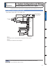
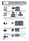
2
Preparation
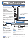
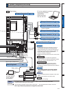
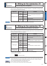
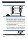
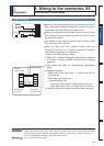
3. Wiring to the connector, X1
Connecting host computer
Caution
This is used for USB connection to a personal computer. It is possible to change the pa-
rameter setting and perform monitoring.
Application Symbol
Connector
Pin No.
Contents
USB signal terminal
VBUS 1
Use for communication with personal
computer.
Dï 2
D+ 3
— 4 Do not connect.
GND 5 Connected to ground of control circuit.
Use commercially available USB mini-B connector for the driver.
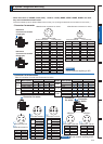
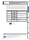
2
Preparation
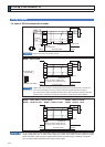
4. Wiring to the connector, X2
Connecting communication connector
This is used for connection to the host controller when two or more units are used.
RS232 and RS485 interfaces are supplied.
Application Symbol
Connector
Pin No.
Contents
Signal ground GND 1 Connected to ground of control circuit.
NC – 2 Do not connect.
RS232 signal
TXD 3
RS232
The transmission / reception method.
RXD 4
RS485 signal
ï 5
RS485
The transmission / reception method.
485+ 6
ï 7
485+ 8
Frame ground FG Shell
Connected with protective earth terminal in
the servo driver.
Connector (plug): 2040008-1 (optional, available from Tyco Electronics)
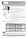
[Connector pin assignment]
(Viewed from cable)
8642
7531
Remarks
Note
Related page
;WR;DUHXVHGIRUWKHVHFRQGDU\FLUFXLW7RFRQQHFWWKHVHWHUPLQDOVWRWKHSULPDU\SRZHU
supply (particularly, the 24 VDC power supply for control, the 24 VDC power supply for brake,
and the 24 VDC power supply for regenerative resistor [H-frame only]), insulation is required.
Do not connect these terminals to the same power supply.
2QO\IRUSRVLWLRQFRQWUROW\SHLVQRWSURYLGHGZLWK;
3´&RQQHFWRU.LWIRU&RPPXQLFDWLRQ&DEOHIRU5656µ