


1-31
1
Before Using the Products
2
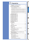
Preparation
3
Connection
4
Setup
5
Adjustment
6
When in Trouble
7
Supplement
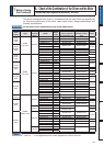
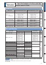
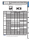
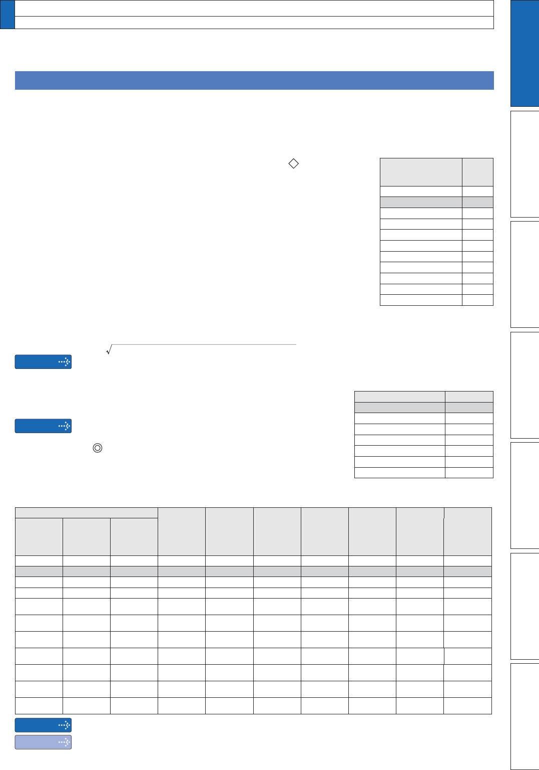
Relationship between Wire Diameter and Permissible Current
Caution
Caution
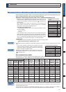
:KHQVHOHFWLQJDFDEOHUHIHUWRWKHIROORZLQJVHOHFWLRQJXLGHVKRZLQJUHODWLRQVKLSEH-
WZHHQFDEOHVSHFLÀFDWLRQDQGFXUUHQWFDUU\LQJFDSDFLW\
Example: Power supply 3-phase, 200 V, 35 A, ambient temperature 30°C
Determine the fundamental permissible current according to the
cable conductor material (example: stranded copper wire). (For the
purpose of this example, the ampere indicated by
is selected from
the table right.)
Next, determine the number of conductors. (In this example, the
cable contains 4 conductors (3 + ground).) Determine the applicable
permissible current using the following formula.
Applicable permissible current
=
IXQGDPHQWDOSHUPLVVLEOHFXUUHQW[FXUUHQWUHGXFWLRQFRHIÀFLHQW[FXUUHQW
FRUUHFWLRQFRHIÀFLHQW
= 37 x 0.7 x 1.414
.
=. 36.6 (A)
This permissible value is larger than 35 A to be carried though the
cable. Therefore, according to the list of recommended eco-cables,
the cable to be selected for the cable with nominal cross section 3.5
mm
2
is a polyethylene-insulated heat-resistant 4-conductor power
FDEOHKDYLQJPPÀQLVK2'DSSUR[PPZLWKVKLHOG
<Supplement>
7KHFXUUHQWFRUUHFWLRQFRHIÀFLHQWLVGHWHUPLQHGXVLQJWKHIROORZLQJIRUPXOD
(Max. permissible temp. – ambient temp.) ÷ 30
7KHFXUUHQWFRUUHFWLRQFRHIÀFLHQWLVGHWHUPLQHGDFFRUGLQJWRWKHFDEOH&KHFNWKHVSHFLÀFDWLRQRIWKHFDEOH
used.
7KHFXUUHQWUHGXFWLRQFRHIILFLHQWLVSURYLGHGIRUWKHFDVH
where the cable (4-conductor cable in the case of example),
is housed in plastic race/sheath, plastic tube, metal race/
VKHDWKPHWDOWXEHRUÁH[LEOHFRQGXLW
Because the neutral conductor is not counted as a wire, the cur-
UHQWUHGXFWLRQFRHIÀFLHQWIRU´RUOHVVµLVDSSOLHGDVLQGLFDWHGE\
(
) in the table right.
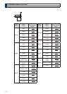
Conductor
Insulation
thickness
(mm)
Sheath
thickness
(mm)
(Reference)
Finish O.D.
(mm)
Max.
conductor
resistance
(20°C)
(W/km)
Test
voltage
(V/1 min.)
Minimum
insulation
resistance
0:NP
(Reference)
Approx.
mass
(kg/km)
Nominal
cross
section
(mm
2
)
Structure
or shape
(wires/mm
2
)
Outside
diameter
(mm)
2 7/0.6 1.8 0.8 1.5 12.0 9.42 1500 2500 170
3.5 7/0.8 2.4 0.8 1.5 13.5 5.30 1500 2500 250
5.5 7/1.0 3.0 1.0 1.5 16.0 3.40 1500 2500 360
8 7/1.2 3.6 1.0 1.5 17.0 2.36 1500 2000 475
14
Circular
compression
4.4 1.0 1.5 19.0 1.34 2000 1500 730
22
Circular
compression
5.5 1.2 1.6 23 0.849 2000 1500 1100
38
Circular
compression
7.3 1.2 1.8 28 0.491 2500 1500 1800
60
Circular
compression
9.3 1.5 2.0 35 0.311 2500 1500 2790
100
Circular
compression
12.0 2.0 2.4 44 0.187 2500 1500 4630
150
Circular
compression
14.7 2.0 2.6 51 0.124 3000 1000 6710
200
Circular
compression
17.0 2.5 2.9 60 0.0933 3000 1500 8990
Caution
Note
5HFRPPHQGHGHFRFDEOH
Wire category: 4-conductor polyethylene-insulated power cable with heat-resistant polyethylene sheath
(Standard: EM JIS C 3605) Maximum permissible temperature: 90°C
6KLHOGZLOOLQFUHDVHÀQLVKRXWVLGHGLDPHWHUE\DSSUR[PP
$SSURSULDWHFDEOHVKRXOGEHVHOHFWHGWRKDYHVXIÀFLHQWDOORZDQFHIRUSDUDPHWHUVVXFKDVRSHUDWLQJDPEL-
ent temperature and current.
&XUUHQWUHGXFWLRQFRHIILFLHQWIXQGDPHQWDOSHUPLVVLEOHFXUUHQWHWFVWDWHGRQWKLVSDJHDUHVXEMHFWWR
change due to e.g. standard revision. Consult cable manufacturers for the latest information.
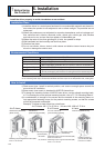
5. Installation
Driver
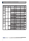
&XUUHQWUHGXFWLRQFRHIILFLHQW
No. of wires in a tube Coefficient
Up to 3 0.70
40.63
5 or 6 0.56
7 to 15 0.49
16 to 40 0.43
41 to 60 0.39
61 or more 0.34
)XQGDPHQWDOSHUPLVVLEOH
current
Stranded conductor
(nominal cross section: mm
2
)
Copper
wire
(unit: A)
2 to 3.5 (excl.) 27
3.5 to 5.5 (excl.) 37
5.5 to 8 (excl.) 49
8 to 14 (excl.) 61
14 to 22 (excl.) 88
11 to 30 (excl.) 115
30 to 38 (excl.) 139
38 to 68 (excl.) 162
60 to 100 (excl.) 217
100 to 150 (excl.) 298
150 to 200 (excl.) 395