


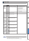

Protective
function
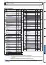
Error code No.
Causes Measures
Main Sub
6-4
Control
power
supply
under-
voltage
protection
11 0
Voltage between P and N of the converter
portion of the control power supply has
IDOOHQEHORZWKHVSHFLÀHGYDOXH
9YHUVLRQ
approx.
9'&
approx.
9$&
9YHUVLRQ
approx.
145 VDC (
approx.
9$&
9YHUVLRQ
approx.
15 VDC
1) Power supply voltage is low.
Instantaneous power failure has
occurred
2) Lack of power capacity...Power supply
voltage has fallen down due to inrush
current at the main power-on.
3)
Failure of servo driver (failure of the circuit)
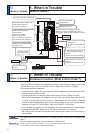
Measure the voltage between lines of
connector and terminal block.
99GULYHU/&/&
9GULYHU99
1) Increase the power capacity. Change the
power supply.
2) Increase the power capacity.
3) Replace the driver with a new one.
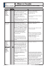
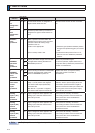
Over-voltage
protection
12 0
Voltage between P and N of the
converter portion of the control power
VXSSO\KDVH[FHHGHGWKHVSHFLÀHGYDOXH
9YHUVLRQ
approx.
9'&
approx.
9$&
9YHUVLRQ
approx.
9'&
approx.
9$&
9YHUVLRQ
approx.
9'&
approx.
9$&
1) Power supply voltage has exceeded
the permissible input voltage. Voltage
surge due to the phase-advancing
capacitor or UPS (Uninterruptible
Power Supply) have occurred.
2) Disconnection of the regeneration
discharge resistor
3) External regeneration discharge
resistor is not appropriate and could
not absorb the regeneration energy.
4) Failure of servo driver (failure of the
circuit)
Measure the voltage between lines of
connector (L1, L2 and L3).
1) Enter correct voltage. Remove a phase-
advancing capacitor.
2) Measure the resistance of the external
resistor connected between terminal B1
- B2 of the driver. Replace the external
UHVLVWRULIWKHYDOXHLV
&KDQJHWRWKHRQHZLWKVSHFLÀHG
resistance and wattage.
4) Replace the driver with a new one.
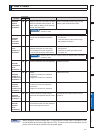
Main power
supply
under-
voltage
protection
(PN)
13 0
Instantaneous power failure has occurred
between L1 and L3 for longer period than
WKHSUHVHWWLPHZLWK3U0DLQSRZHU
RIIGHWHFWLQJWLPHZKLOH3U/9WULS
selection at the main power-off) is set
to 1. Or the voltage between P and N of
the converter portion of the main power
VXSSO\KDVIDOOHQEHORZWKHVSHFLÀHG
value during Servo-ON.
9YHUVLRQ
approx.
9'&
approx.
55 VAC)
9YHUVLRQ
approx.
9'&
approx.
75 VAC)
9YHUVLRQ
approx.
9'&
approx.
125 VAC)
1) Power supply voltage is low.
Instantaneous power failure has
occurred
2) Instantaneous power failure has
occurred.
3) Lack of power capacity...Power supply
voltage has fallen down due to inrush
current at the main power-on.
4) Phase lack...3-phase input driver has
been operated with single phase input.
5)
Failure of servo driver (failure of the circuit)
Measure the voltage between lines of
connector (L1, L2 and L3).
1)
Increase the power capacity. Change the
power supply. Remove the causes of the
shutdown of the magnetic contactor or the
main power supply, then re-enter the power.
6HWXSWKHORQJHUWLPHWR3U0DLQ
power off detecting time). Set up each
phase of the power correctly.
3)
Increase the power capacity. For the capacity,
UHIHUWR3'ULYHUDQG/LVWRI$SSOLFDEOH
Peripheral Equipments" of Preparation.
4) Connect each phase of the power supply
(L1, L2 and L3) correctly. For single phase,
9DQG9GULYHUXVH/DQG/
5) Replace the driver with a new one.
Main power
supply
under-
voltage
protection
(AC)
1
6
1. When in Trouble
When in Trouble
Protective function (Detail of error code)