


2-77
1
Before Using the Products
2
Preparation
3
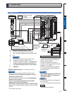
Connection
4
Setup
5
Adjustment
6
When in Trouble
7
Supplement
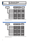
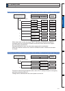
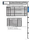
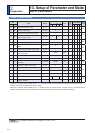
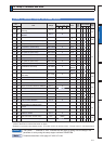
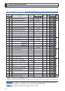
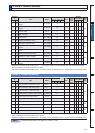
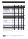
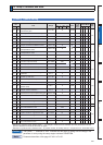
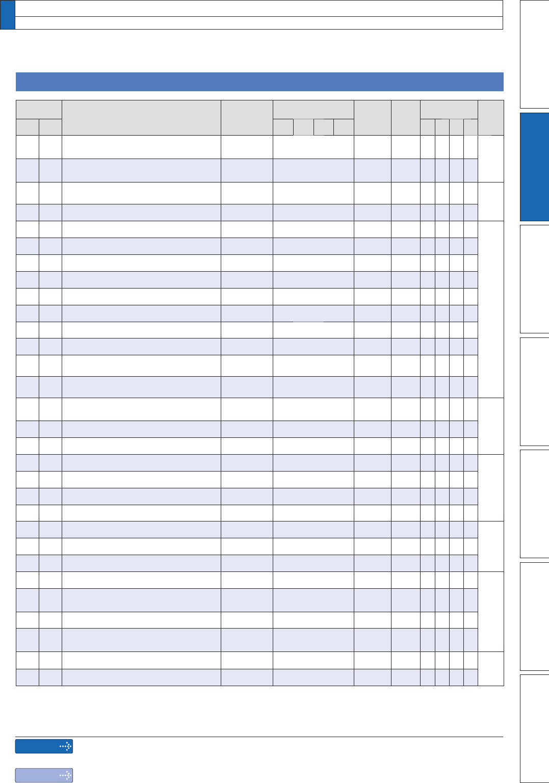
>&ODVV@9HURFLW\7RUTXH)XOOFORVHGFRQWURO
Parametr
No.
Title Range
Default
Unit
Turning
on of
power
supply
Related
Control Mode Detail
page
Class
No.
A,B
-frame
C
-frame
D,E,F
-frame
G,H
-frame
PSTF
300
Speed setup, Internal/External
switching
0 to 3 0 ï
4-25
301
Speed command rotational direction
selection
0 to 1 0 ï
302
Input gain of speed command 10 to 2000 500
(r/min)/
V
4-26
303
Reversal of speed command input 0 to 1 1 ï
304
1st speed of speed setup
ïWR
0r/min
4-27
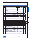
305
2nd speed of speed setup
ïWR
0r/min
306
3rd speed of speed setup
ïWR
0r/min
307
4th speed of speed setup
ïWR
0r/min
308
5th speed of speed setup
ïWR
0r/min
309
6th speed of speed setup
ïWR
0r/min
310
7th speed of speed setup
ïWR
0r/min
311
8th speed of speed setup
ïWR
0r/min
312
Acceleration time setup 0 to 10000 0
ms/
(1000r/min)
313
Deceleration time setup 0 to 10000 0
ms/
(1000r/min)
314
Sigmoid acceleration/ deceleration
time setup
0 to 1000 0 ms
4-28
315
Speed zero-clamp function selection 0 to 3 0 ï
316
Speed zero clamp level 10 to 20000 30 r/min
317
Selection of torque command 0 to 2 0 ï
4-29
318
Torque command direction selection 0 to 1 0 ï
319
Input gain of torque command 10 to 100 30
0.1V/100%
*
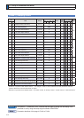
320
Input reversal of torque command 0 to 1 0 ï
321
Speed limit value 1 0 to 20000 0 r/min
4-30322
Speed limit value 2 0 to 20000 0 r/min
323
External scale selection 0 to 2 0 ï
324
Numerator of external scale division 0 to 2
20
0 ï
4-31
325
Denominator of external scale
division
1 to 2
20
10000 ï
326
Reversal of direction of external scale
0 to 1 0 ï
327
External scale Z phase disconnection
detection disable
0 to 1 0 ï
328
Hybrid deviation excess setup 1 to 2
27
16000
Command
unit
4-32
329
Hybrid deviation clear setup 0 to 100 0
Revolution
'HÀQLWLRQRIV\PEROVXQGHU´3RZHU2II2QµLIDFKDQJHLVPDGHLWZLOOEHUHÁHFWHGXSRQWKHSDUDPHWHUZKHQWKH
power to the driver is turned off and then on again.
*
'HÀQLWLRQRIV\PEROVXQGHU´5HODWHGPRGHµ3SRVLWLRQFRQWURO6YHORFLW\FRQWURO7WRUTXHFRQWURO)IXOOFORVHGFRQWURO
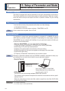
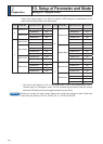
13.
Setup of Parameter and Mode
List of Parameters
Caution
Note
The symbol “
*
” attached to “Unit”. indicates that the digits of setting unit will change if the
parameter is set by using the setup support software PANATERM.
Parameter describes of this page is P.4-25 to P.4-32.