


1-11
1
Before Using the Products
2
Preparation
3
Connection
4
Setup
5
Adjustment
6
When in Trouble
7
Supplement
1 Before Using
the Products
2. Driver
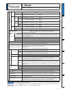
Specifications (Velocity, position, torque, full-closed control type)
%DVLF6SHFLÀFDWLRQV
Input power
100V
Main circuit
Single phase, 100 to 120V
+10%
50/60Hz
–15%
Control circuit
Single phase, 100 to 120V
+10%
50/60Hz
–15%
200V
Main
circuit
A to
D-frame
Single/3-phase, 200 to 240V
+10%
50/60Hz
–15%
E to
H-frame
3-phase, 200 to 230V
+10%
50/60Hz
–15%
Control
circuit
A to
D-frame
Single phase, 200 to 240V
+10%
50/60Hz
–15%
E to
H-frame
Single phase, 200 to 230V
+10%
50/60Hz
–15%
400V
*1
Main circuit
3-phase, 380 to 480V
+10%
50/60Hz
–15%
Control circuit
DC24V ± 15%
Withstand voltage
Primary to earth: withstand 1500 VAC, 1 min, (sensed current: 20 mA) [100V/200V]
withstand 1960 VAC, 1 min, (sensed current: 20 mA) [400V]
* 400V control circuit is excluded.
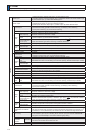
Environment
temperature
$PELHQWWHPSHUDWXUHÝ&WRÝ&IUHHIURPIUHH]LQJ
6WRUDJHWHPSHUDWXUH²Ý&WRÝ&
(Max. temperature guarantee: 80
Ý
C for 72 hours
free from condensation
*2
)
humidity Both operating and storage : 20 to 85%RH or less (free from condensation
*2
)
Altitude Lower than 1000m
Vibration 5.88m/s
2
RUOHVVWR+]1RFRQWLQXRXVXVHDWUHVRQDQFHIUHTXHQF\
Control method IGBT PWM Sinusoidal wave drive
Encoder feedback
17-bit (131072 resolution) absolute encoder, 7-wire serial
20-bit (1048576 resolution) incremental encoder, 5-wire serial
Feedback scale feedback
A/B phase, initialization signal defferential input.
Manufacturers that support serial communication scale:
Mitsutoyo Corp.
Magnescale Co., Ltd. (old Sony Manufacturing Systems Corp.)
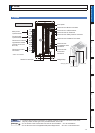
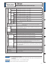
Parallel I/O connector
Control signal
Input
General purpose 10 inputs
The function of general-purpose input is selected by parameters.
Output
General purpose 6 outputs
The function of general-purpose input is selected by parameters.
Analog signal
Input 3 inputs (16Bit A/D : 1 input, 12Bit A/D : 2 inputs)
Output 2 outputs (Analog monitor: 2 output)
Pulse signal
Input
2 inputs (Photo-coupler input, Line receiver input)
Photocoupler input is compatible with both line driver I/F and open collector I/F.
Line receiver input is compatible with line driver I/F.
Output
4 outputs ( Line driver: 3 output, open collector: 1 output)
Feed out the encoder feedback pulse (A, B and Z-phase) or feedback scale pulse (EXA,
EXB and EXZ-phase) in line driver. Z-phase and EXZ-phase pulse is also fed out in open
collector.
Communication
function
USB Connection with PC etc.
RS232 1 : 1 communication to a host.
RS485 1 : n communication to a host.
Safety function Used for functional safety.
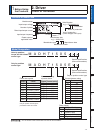
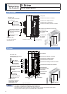
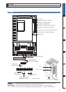
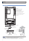
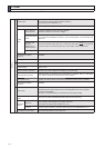
Front panel
(1) 5 keys (MODE, SET, UP, DOWN, SHIFT) (2) LED (6-digit)
(3) Monitor connector (Analog monitor output (2ch), Digital monitor output (1ch))
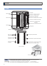
Regeneration
A, B, G and H-frame: no built-in regenerative resistor (external resistor only)
C to F-frame: Built-in regenerative resistor (external resistor is also enabled.)
Dynamic brake
A to G-frame: Built-in (external resistor is also available to G-frame)
H-frame: External only
Control mode
Switching among the following 7 mode is enabled,
3RVLWLRQFRQWURO9HORFLW\FRQWURO7RTXHFRQWURO3RVLWLRQ9HORFLW\FRQWURO
3RVLWLRQ7RUTXHFRQWURO9HORFLW\7RUTXHFRQWURO)XOOFORVHGFRQWURO
Caution
Related page
7KHVSHFLÀFDWLRQRXWRI-DSDQ
*2
Air containing water vapor will become saturated with water vapor as the temperature falls, causing dew.
3´,QVWDOODWLRQRI'ULYHUµ3´,QVWDOODWLRQRI0RWRUµ