


6-23
1
Before Using the Products
2
Preparation
3
Connection
4
Setup
5
Adjustment
6
When in Trouble
7
Supplement
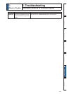
&ODVVLÀFDWLRQ
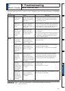
Causes Measures
Parameter
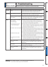
Setup of the control mode is not
correct.
,I\RXVHWXS3UWR9HORFLW\FRQWUROPRGHE\PLVWDNHDW
position control mode, the motor runs slowly at servo-ON due to
VSHHGFRPPDQGRIIVHW&KDQJHWKHVHWXSRI3UWR
Adjustment
Gain adjustment is not proper. ,QFUHDVHWKHVHWXSRI3UVWYHORFLW\ORRSJDLQ(QWHUWRUTXH
ÀOWHURI3UDQGLQFUHDVHWKHVHWXSRI3UDJDLQ
Velocity and position command
are not stable.
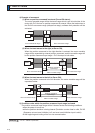
&KHFNWKHPRWRUPRYHPHQWZLWKFRQQHFWRU;RIWKHIURQWSDQHO
or the waveform graphic function of the PANATERM. Review the
wiring, connector contact failure and controller.
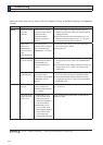
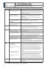
Wiring
Each input signal of Connector
;LVFKDWWHULQJ
1) Servo-ON signal
2) Positive/Negative direction
torque limit input signal
3) Deviation counter input signal
4) Speed zero clamp signal
5) Command pulse inhibition
input
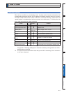
&KHFNWKHZLULQJDQGFRQQHFWLRQEHWZHHQ3LQDQGRIWKH
&RQQHFWRU;XVLQJWKHGLVSOD\IXQFWLRQRI,2VLJQDOVWDWXV
Correct the wiring and connection so that the Servo-ON signal
can be turned on normally. Review the controller.
2) Check the wiring and connection between Pin-18 and 17, 16 and
RIWKH&RQQHFWRU;XVLQJWHVWHURURVFLOORVFRSH&RUUHFWWKH
wiring and connection so that Positive/Negative direction torque
limit input can be entered normally.
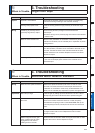
&KHFNWKHZLULQJDQGFRQQHFWLRQEHWZHHQ3LQDQGRIWKH
&RQQHFWRU;XVLQJGLVSOD\IXQFWLRQRI,2VLJQDOVWDWXV&RUUHFW
the wiring and connection so that the deviation counter input can
be turned on normally. Review the controller.
4) Check the wiring and connection between Pin-26 and 41of the
&RQQHFWRU;XVLQJ'LVSOD\IXQFWLRQRI,2VLJQDOVWDWXV&RUUHFW
the wiring and connection so that the speed zero clamp input can
be entered normally. Review the controller.
5) Check the wiring and connection between Pin-33 and 41of the
&RQQHFWRU;XVLQJGLVSOD\IXQFWLRQRI,2VLJQDOVWDWXV&RUUHFW
the wiring and connection so that the command pulse inhibition
input can be entered normally. Review the controller.
Noise is on the velocity
command.
8VHDVKLHOGFDEOHIRUFRQQHFWLQJFDEOHWRWKH&RQQHFWRU;
6HSDUDWHWKHSRZHUOLQHDQGVLJQDOOLQHFPRUORQJHULQWKH
separate duct.
Slip of offset Check the voltage between Pin-14 and 15 (speed command input)
using a tester or an oscilloscope.
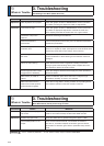
Noise is on the position
command.
8VHDVKLHOGFDEOHIRUFRQQHFWLQJFDEOHWRWKH&RQQHFWRU;
6HSDUDWHWKHSRZHUOLQHDQGVLJQDOOLQHFPRUORQJHULQWKH
separate duct.
6
3. Troubleshooting
When in Trouble
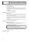
Unstable Rotation (Not Smooth),
Motor Runs Slowly Even with Speed Zero at Velocity Control Mode
Related page
3´'HWDLOVRISDUDPHWHUµ3´,QSXWVDQGRXWSXWVRQFRQQHFWRU;µ
3´2XWOLQHRI6HWXSVXSSRUWVRIWZDUH´3$1$7(50µ