2-87
1
Before Using the Products
2
Preparation
3
Connection
4
Setup
5
Adjustment
6
When in Trouble
7
Supplement
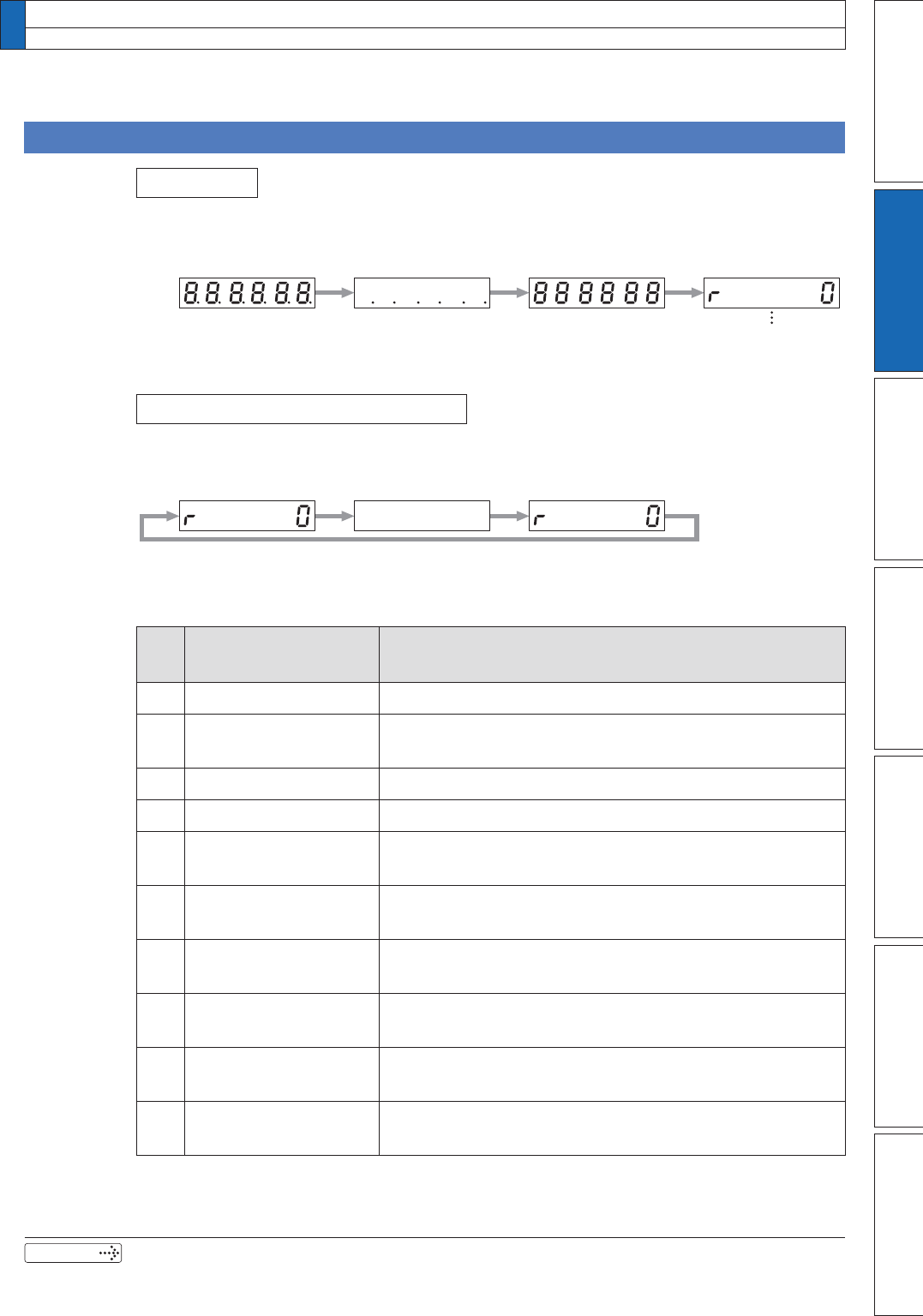
approx. 2 sec approx. 0.6 sec approx. 0.6 sec
Initial display of LED
(Determined by the setup of Parameter, Pr5.28 "Initial status of LED".)
approx. 0.8 sec
Repeatedly(during continuous alarm)
0.3 sec
Initial Status of the Front Panel Display (7 Segment LED)
Status
Front panel display shows the following after turning on the power of the driver.
Upon Occurrence of an Alarm
If a driver alarm is generated, the front panel display shows the following repeatedly.
Below shows possible cause of an alarm.
alarm
No.
Alarm Content
A0 Overload protection Load factor is 85% or more the protection level.
A1
Over-regeneration
alarm
Regenerative load factor is 85% or more the protection
level.
A2 Battery alarm Battery voltage is 3.2 V or lower.
A3 Fan alarm Fan has stopped for 1 sec.
A4
Encoder
communication alarm
The number of successive encoder communication errors
H[FHHGVWKHVSHFLÀHGYDOXH
A5
Encoder overheat
alarm
The encoder detects overheat alarm.
A6
Oscillation detection
alarm
Oscillation or vibration is detected.
A7
Lifetime detection
alarm
The life expectancy of capacity or fan becomes shorter
WKDQWKHVSHFLÀHGWLPH
A8
External scale error
alarm
The external scale detects the alarm.
A9
External scale
communication alarm
The number of successive external scale communication
HUURUVH[FHHGVWKHVSHFLÀHGYDOXH
15. How to Use the Front Panel
Setup
Related page
3´'HWDLOVRI3DUDPHWHUµ


