


2-15
1
Before Using the Products
2
Preparation
3
Connection
4
Setup
5
Adjustment
6
When in Trouble
7
Supplement
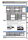
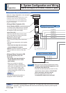
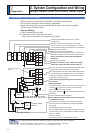
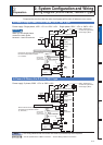
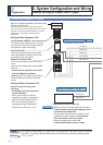
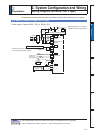
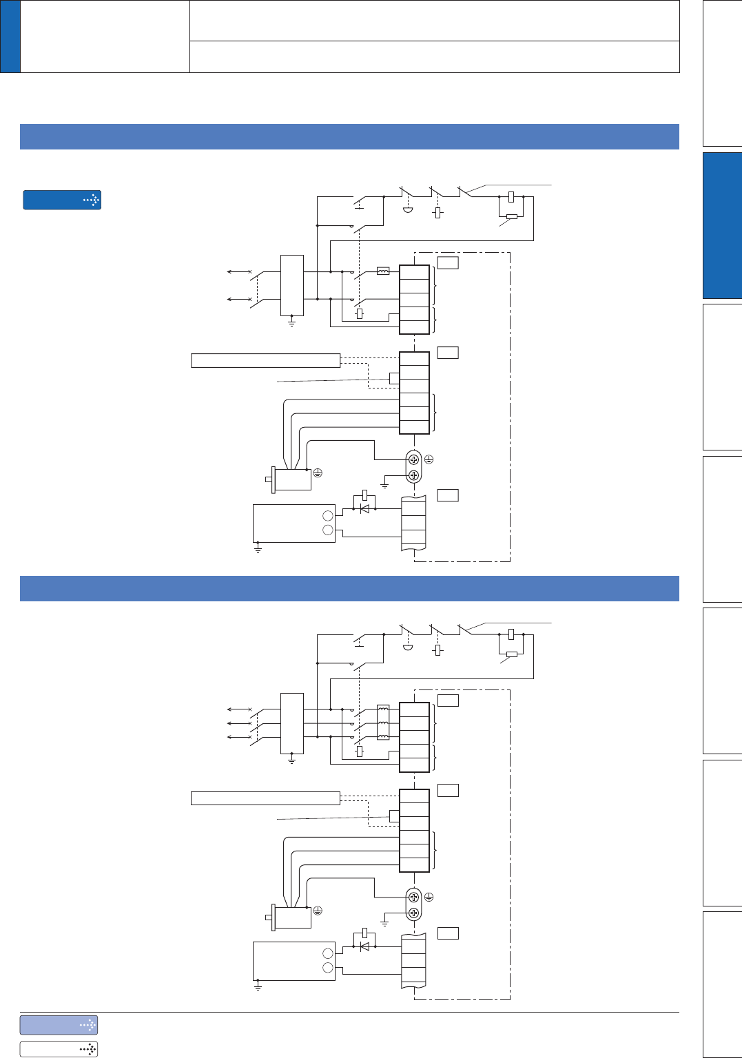
Compose the circuit so that the main circuit power will be shut off when an error occurs.
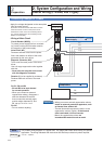
In Case of Single Phase, A to D-frame, 100 V / 200 V type
Noise filter
Noise filter
Motor
37
ALM+
L2
L3
L1C
L2C
B1
MC
MCCB
B3
B2
U
V
W
L1
$/0ï
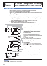
External regenerative resistor
Remove the short wire when you connect
the external regenerative resistor.
(C, D-Frame)
External regenerative resistor
36
L
ON
Motor
37
ALM+
L2
L3
L1C
L2C
B1
MC
MCCB
ALM
OFF
B3
B2
U
V
W
L1
Coil surge suppression units
Built-in thermostat of
an external regenerative
resistor (light yellow)
Built-in thermostat of
an external regenerative
resistor (light yellow)
$/0ï
Red
White
Black
Green or
Green/Yellow
Red
White
Black
Green or
Green/Yellow
XA
XB
X4
36
L
ON
MC
ALM
ALM
OFF
MC
ALM
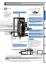
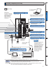
Main power
supply
Control power
supply
Motor
connection
Main power
supply
Control power
supply
Motor
connection
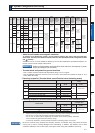
Power supply Single phase, 100V to 120V–15% +10% Single phase, 200V to 240V–15% +10%
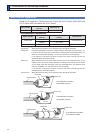
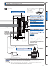
Power supply 3-phase, 200V to 240V–15% +10%
XA
XB
X4
When you use single phase,
connect the main power
between L1 and L3 terminals.
Coil surge suppression units
Remarks
Remove the short wire when you connect
the external regenerative resistor.
(C, D-Frame)
* These colors
are used for
optional cable.
* These colors
are used for
optional cable.
Insulated
DC12 to 24V
(±5%)
+
ï
Insulated
DC12 to 24V
(±5%)
+
ï
In Case of 3-Phase, A to D-frame, 200 V type
2
Preparation
2.
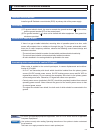
6\VWHP&RQÀJXUDWLRQDQG:LULQJ
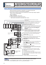
Wiring Diagram (A to D-frame, 100/200 V type)
Note
Related page
The wiring indicated with the broken line shall be provided only when required.
3´6SHFLÀFDWLRQVRI0RWRUFRQQHFWRUµ3´:LULQJPHWKRGWRFRQQHFWRUµ