


2-57
1
Before Using the Products
2
Preparation
3
Connection
4
Setup
5
Adjustment
6
When in Trouble
7
Supplement
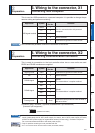
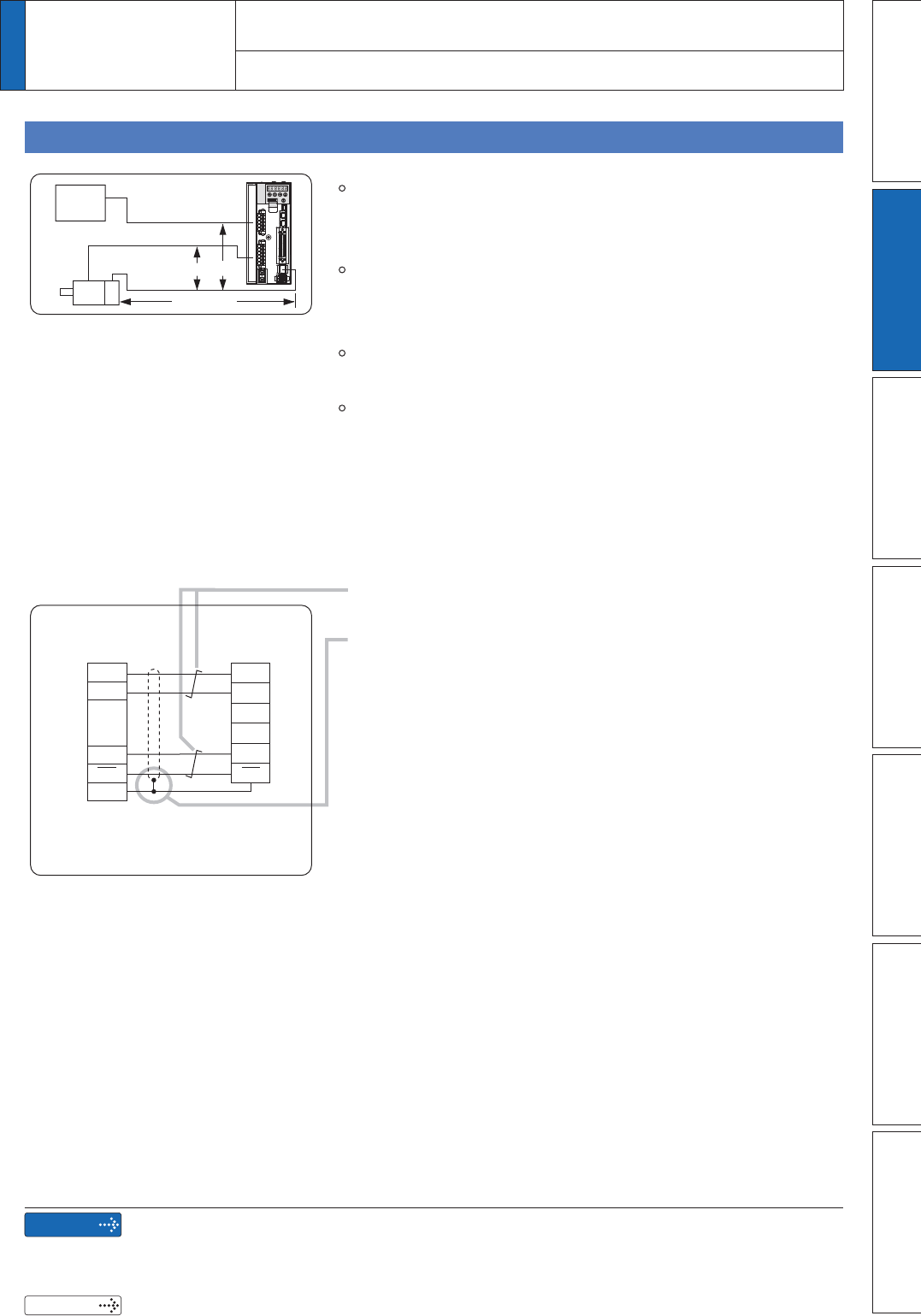
Tips on Wiring
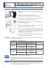
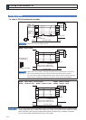
Motor
Encoder
30cm or more
20m max.
Maximum cable length between the driver and the motor to be
20m. Consult with a dealer or distributor if you want to use the
longer cable than 20m. (Refer to the back cover.)
Keep this wiring away from the main circuit by 30 cm or more.
Don't guide this wiring through the same duct with the main,
nor bind them together.
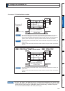
The voltage of input power to encoder side connector should
be in the range 4.90–5.25 VDC.
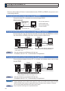
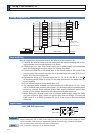
When you make your own encoder junction cable (for
connectors, refer to P.7-111, "Options (Connector Kit for Motor
and Encoder connection)" of Supplement.
1) Refer to the Wiring Diagram below.
2) Cable to be : Shielded twisted pair cable with core diameter
of 0.18mm
2
or larger (AWG24), and with higher bending
resistance.
3) Use twisted pair cable for corresponding signal/power
wiring.
4) Shielding treatment
6KLHOG ZDOO RI WKH GULYHU VLGH ,W VROGHUV WKH VKHOO RI
Connector X6.
6KLHOGZDOORIWKHPRWRUVLGH
manufactured by JAE
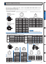
Small type motor (50W to 750W): connect to 6-pins
Large type motor (0.9W to 15.0kW): connect to 9-pins
5) Connect nothing to the empty terminals of each connector.
Power
supply
Encoder
junction cable
Encoder side
connector
Driver side
Connector X6
E5V
E0V
PS
PS
PS
PS
FG
E5V
E0V
2
Preparation
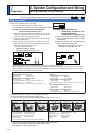
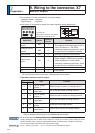
8. Wiring to the connector, X6
Connection to Encoder
Remarks
Related page
;WR;DUHXVHGIRUWKHVHFRQGDU\FLUFXLW7RFRQQHFWWKHVHWHUPLQDOVWRWKHSULPDU\SRZHU
supply (particularly, the 24 VDC power supply for control, the 24 VDC power supply for brake,
and the 24 VDC power supply for regenerative resistor [H-frame only]), insulation is required.
Do not connect these terminals to the same power supply.
3´&RQQHFWRU.LWIRU(QFRGHUµ